VAC V200 POSITIONER Manuel

92077r14
V200 POSITIONER
www.vacaccessories.com
1
V200 FEEDBACK OPTION

92077r14
www.vac.se
V200 POSITIONER
2
1 INTRODUCTION.................................................................................. 4
1.1 Principle of Operation.............................................................. 4
1.2 ProductIdentication............................................................... 4
1.3 Safety Instructions................................................................... 4
2 FEEDBACK INSTALLATION.............................................................. 5
2.1 Connections ............................................................................ 5
2.2 Front cover and indicator ........................................................ 5
2.2.1 Removing the front cover ........................................................ 5
2.2.2 Removing the indicator ........................................................... 5
2.3 4-20mA Transmitter installation............................................... 6
2.3.1 Gearwheel installation............................................................. 6
2.3.2 Potentiometer installation........................................................ 6
2.3.3 4-20mA Transmitter setup ....................................................... 7
2.3.4 Connecting the control signal.................................................. 7
2.3.5 4-20mA Transmitter Calibration............................................... 8
2.3.6 Trouble shooting - Reset and Calibration................................ 8
2.4 Switch option installation......................................................... 9
2.4.1 Switch and cam installation..................................................... 9
2.4.2 Electrical installation................................................................ 9
2.4.3 Switch calibration .................................................................... 9
3 SPARE PARTS ................................................................................... 10
3.1 Exploded drawing feedback options ....................................... 10
3.2 Spare parts list feedback options ............................................ 11
4 SPECIFICATIONS............................................................................... 12
4.1 Specicationsfeedbackoptions.............................................. 12
CONTENTS

92077r14
V200 POSITIONER
www.vacaccessories.com
3
1 INTRODUCTION
1.1 Principle of operation
The V200 feedback options allows for accurate
positionfeedback,whereon-o(open/closed)
indication(switches)orcontinuous4-20mA
transmission(orsimplepotentiometer)isrequired.
Anyfeedbackmodulecanbefactoryoreldinstalled
inside the V200 positioner housing with no special
parts or mounting brackets. This creates a very
compact and simple package that is completely
sealed.
The various feedback options are connected to the
positionermaindriveshaft(1)whichisconnectedto
the actuator shaft via the positioner spindle, assisting
inamoredirectandaccurateactuator/valvemonitoring.
A position change moves the V200 spindle and switch
cam(2)foron-o(oropen/closed)indication.
The4-20mApositiontransmittermkII(3)respondsto
changesproportionallyintheactuator/valvepackage.
It is recommended that the V200 positioner be
calibrated before installing feedback options.
CAUTION:
Beware of moving parts
when positioner is operated!
1.3 Safety instruction
CAUTION: Beware of parts with live voltage!
A voltage, which is normally not dangerous, is supplied to the positioner. Avoid touch-
ing live parts and bare wires as well as short circuiting live parts and the housing.
1.2 Product identication
TheV200identicationtags,Serialnumbertag(1),product-
modeltag(2)andfeedbackoptiontag(3),areplacedasshown.
The product model tag contains information on control signal,
maximum working pressure and temperature ranges.
Other information can be shown depending on the model.
Not for use in Hazardous locations.
Feedback options described in this manual
are for for General purpose only.
1
3
2

92077r14
www.vac.se
V200 POSITIONER
4
2. FEEDBACK INSTALLATION
2.1 Connections
– Grounding point
1. – Terminal block, switches
2 X 3 Connections
MaximumcablesizeAWG11(4mm2)
2. – Terminal block, Position Transmitter
MaximumcablesizeAWG13(2.5mm2)
1
1
2.2 Front cover and indicator
2.2.1 Removing the front cover
Loosenthetwoscrews(1)and
remove the front cover.
2.2.2 Removing the indicator
Pulltheindicator(2)straightup,itisafrictiont.
Important Note!
Note the indicator’s position so it
can be installed in the same position.
Installing the indicator
Install the indicator in place over the drive
shaft and press it straight down.
Be sure to press the indicator completely down
so that it does not interfere with the indicator
cover(clearcover).
Turn the indicator to the proper display
position.
2
1
2

92077r14
V200 POSITIONER
www.vacaccessories.com
5
2.3 4-20mA transmitter installation
2.3.1 Gearwheel installation
1. Remove the front cover and indicator
ontheV200positioner.(seepage4)
2.RemoveIndicatorscrew(1).
3.Installthegearwheel(2)sothatitalignsover
thecamlockingnutscrew(3).
4. Secure the gearwheel with the
Indicatorscrew(1).
2.3.2 Potentiometer installation
1.Installthepotentiometermodule(4)in
the designed section of the unit as
shown. Tighten the screw that secures
the pot arm and spring.
The pot gearwheel should be aligned
and secured to the larger gearwheel.
2.Installthepotentiometerboard(5)orthe
4-20mAtransmittermodule(6)intothe
designed position and tighten the respective
screws.
3. When used for the 4-20mA feedback, secure
thepotentiometerconnector(7)tothe
transmitter(6).Forpotentiometeruseonly,
theconnector(7)willattachtotheterminal
block(5)andbeusedwithanexternalposition
transmitter.
1
4
3
2
1
5
6
7

92077r14
www.vac.se
V200 POSITIONER
6
2.3.3 4-20mA transmitter setup
1. Determine the direction for
increasingmAoutput.Direct(CCW)
orReverse(CW).
2. The direction of rotation is simply
determined by watching the positioner
driveshaft(1).
3. CCW rotation: the potentiometer lead
connector(2)ttedwiththeBlackorBlue
colored lead facing to the left.
4. CW rotation: the potentiometer lead
connector(2)ttedwiththeBlackorBlue
colored lead facing to the right.
The position transmitter can be calibrated in a
range from 25° up to 115°.
25°-70°withJumper(3).
70°-115°noJumper(3).
The Position Transmitter is
shipped for direct (CCW)
turning, range 0-90°
2.3.4 Connecting the control signal
1. Connect the signal cable to the proper
poleontheterminalblock(1).
MaximumcablesizeAWG13(2.5mm2)1
1
2
2
3

92077r14
V200 POSITIONER
www.vacaccessories.com
7
1. Power up the current loop.
2.Connectalowohmicamperemeteroverthetestpoints(5).
3.Setthevalve/actuatortotheclosed/zeroposition(4mA).
4.Turnthefeedbackpotentiometershaft(6)with
a screw driver until you read 3.7 - 3.9 mA on the meter.
5.Adjustthetrimpotentiometer(7)markedzero
so that the meter reads 4mA.
6.Setthevalve/actuatortotheopenposition(20mA).
7.Adjustthetrimpotentiometer(8)marked
span until the meter reads 20mA.
8.Re-checkthezeroposition(4mA)and
makeneadjustmentsifnecessary.
A very basic calibration can be accomplished
without a meter, using the two LED’s.
Red LED lights up below 3.9mA, Green LED lights up above 20.1mA.
2.3.5 4-20mA transmitter Calibration
Make sure V200E/P has rst been properly calibrated!
Pot adjustment.eps
5
6
6
6
5
8
7
7 8

92077r14
www.vac.se
V200 POSITIONER
8
NOTE: Make sure V200E/P has rst been properly calibrated!
1.TurntheZERO-pot(2)morethan22turnscounterclockwise.
2.TurntheZERO-pot(2)5-6turnsclockwise.
3.TurntheSPAN-pot(3)morethan22turnscounterclockwise.
4.TurntheSPAN-pot(3)10-12turnsclockwise.
5.TurntheFEEDBACK-pot(1)until3.7-3.9mAisachieved.
6.AdjusttheZERO-pot(2)clockwiseto4mA.
7. Open the valve.
8.AdjusttheSPAN-pot(3)to20mA.
9. Close the valve.
10.Repeat(steps6-9)untiltheunitisproperlyset.
If you are unable to properly zero and span the feedback, the potentiometers
could be out of factory settings. In order to get back to factory settings please
follow the steps 1-8 below.
2.3.6 Trouble shooting - Reset and Calibration

92077r14
V200 POSITIONER
www.vacaccessories.com
9
2.4 Switch option Installation
2.4.1 Switch and cam installation
1. Remove the front cover and indicator
ontheV200positioner.(seepage4)
2.RemovetheIndicatorscrew(1).
3.Installtheswitchcamassembly(2)inthe
positioner drive slot and secure the cams with
screw(3).Installtheswitchmodule(4)and
tightenthethreescrews(5).
2.4.2 Electrical installation
Connectyourcontrolsystem/equipmentcables
totheterminalblocks(6)
MaximumcablesizeAWG11(4mm2)
2.4.3 Switch calibration
The switch activating points can be adjusted by
turningthefrictionloadedcams(7,8)usingascrew-
driver in the slots on the cams.
1.Withameter,settherstcamtoeithernormally
open(NO)ornormallyclosed(NC)atitsdesired
position.
2.Strokethevalve/actuatortothedesired
position for the second switch and adjust
the second cam.
3. Double check the two activation points.
NOTE: Use a non magnetic screwdriver when
adjusting reed switch cams!
3
1
8
7
6
4
5
2
92077r14
www.vac.se
V200 POSITIONER
10
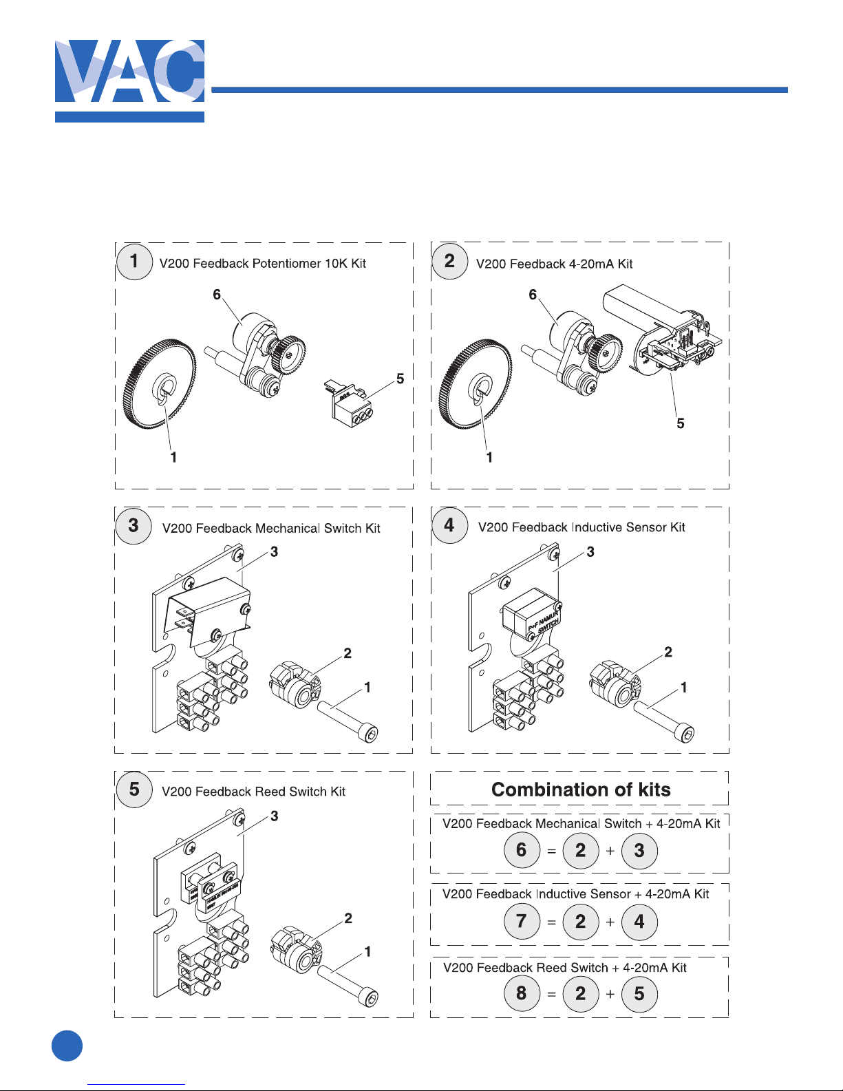
3.1 Exploded drawing Feedback options
3. SPARE PARTS
Autres manuels pour V200 POSITIONER
3
Table des matières
Autres manuels VAC Positionneur de vanne

VAC
VAC V200 Series Instructions d'installation et d'utilisation

VAC
VAC V200 Series Manuel

VAC
VAC TZIDC Guide rapide

VAC
VAC V200 POSITIONER Manuel utilisateur

VAC
VAC D400 Manuel utilisateur

VAC
VAC V200 POSITIONER Manuel utilisateur

VAC
VAC D500 Manuel utilisateur

VAC
VAC D400 Manuel de formation

VAC
VAC V200 POSITIONER Manuel d'utilisation et d'entretien


