UTILITY ROCKET V1.0 Manuel utilisateur

Rocket Access Point V1.0
User Guide
June 2011

Rocket Access Point
ii
Notices
The contents of this document and the associated software are the property of Utility Associates, Inc.
Any reproduction in whole or in part is strictly prohibited. For additional copies of this document or
software, please contact Utility Associates.
Information in this document is subject to change without notice and does not represent a
commitment on the part of Utility Associates. The software as described in this document is furnished
under a license agreement or non-disclosure agreement. The software may be used or copied only in
accordance with the terms of the agreement. It is against the law to copy said software on any medium
except as specifically allowed in the license or non-disclosure agreement. No part of this manual may
be reproduced or transmitted in any form or by any means, for any purpose, without the express
written permission of Utility Associates. Companies, names, and data used in examples herein are
fictitious unless otherwise noted.

Rocket Access Point
iii
Table of Contents
Hardware Setup Overview..............................................................................................................................................1
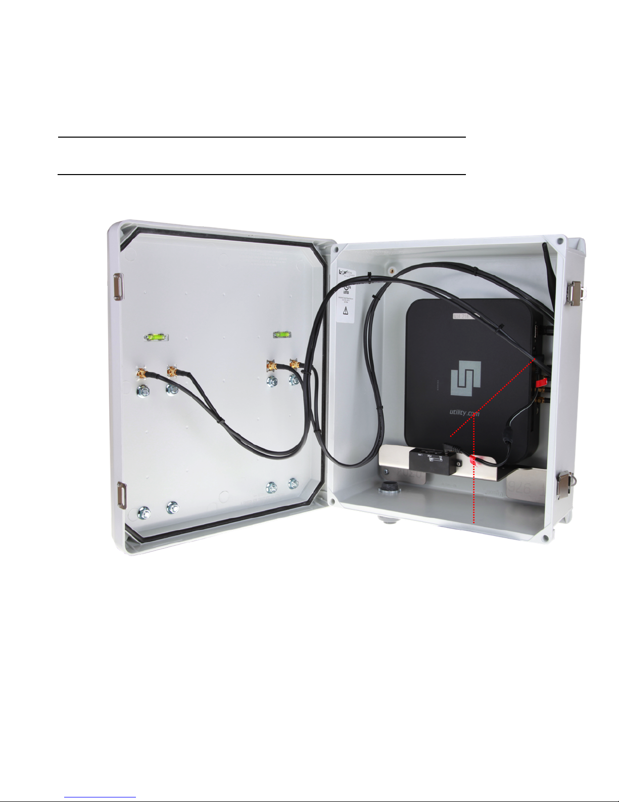
Connecting cables within the RAP’s Enclosure ..................................................................................................2
Connecting cables outside the RAP’s Enclosure................................................................................................7
Configuring your RAP Overview ...................................................................................................................................9
Basic Setup.......................................................................................................................................................................9
Main Page...................................................................................................................................................................... 10
Wireless Page ............................................................................................................................................................... 11
Setting up your wireless configuration .............................................................................................................. 12
Network Mode............................................................................................................................................................. 13
Services Page ............................................................................................................................................................... 14
Setting RAP Services.................................................................................................................................................. 15
System Page ................................................................................................................................................................. 16
System Administration............................................................................................................................................. 17
FAQ .................................................................................................................................................................................. 18

Rocket Access Point
1
Hardware Setup Overview
Your RAP is a self-contained unit within its own housing. The unit has been factory setup with its default configuration
however, you should familiarize yourself with each connection as a reference for any possible maintenance and or
trouble shooting in the unlikely event that your RAP does not function as designed.

Rocket Access Point
2
Connecting cables within the RAP’s Enclosure
1. Ensure that the unit is powered off.
a. This is accomplished by removing the barrel connector on the cable with the RED tag on it; please insure
this connector does not come in connect with any metallic objects.
i. Additionally ensure that NO RJ45 external cables are attached to the POE switch port located on
the front of the internal mount that secures the RAP unit in the enclosure.
a

Rocket Access Point
3
2. Connect the RAP’s internal antenna cables to each of the respective ports located on the inside front enclosures
housing.
a. Ensure that the long ‘rubber duck” barrel antenna is attached to the 2.4 GHz port located directly next to
the DB9 connection on the same side as the 5 GHz antenna connectors.
2A
2B
a
Inside front enclosure
Rubber duck

Rocket Access Point
4
3. Once all antenna connections have been attached correctly, attach the barrel connector to the RAP
power access port located directly above the console port.
Note: Please make sure that these connections are made properly and tightened accordingly.
4. Connect the power cable to POE adapter.
4

Rocket Access Point
5
Note: The following picture is the side view of the Rocket inside the RAP. The Ethernet, Console, and 802.11 5GHz
(A&B) ports are diificult to see while housed inside the RAP’s shell.
From top to bottom: Console port, RAP's Ethernet ports, top and bottoms WiFi ports on the inside of the RAP’s
enclosure.
802.11 5GHz-A
Console Port
Ethernet Ports
Rubber duck 2.4 GHz
802.11 5GHz-B

Rocket Access Point
6
5. Connect an Ethernet cable from one of the RAP's three (3) Ethernet LAN ports to the POE Switch port
located on the front of the internal mount that secures the RAP unit in the enclosure on the inside of
the RAP’s enclosure.
Note: Make sure that you do not connect the network cable into the console port located directly above the Ethernet
LAN ports.
6. Connect your POE network patch cable into the POE Switch port located on the front of the internal
mount that secures the RAP unit in the enclosure on the inside of the RAP’s enclosure.
7. Plug any additional Ethernet patch cables that lead to other access points or routers (Optional).
5
6

Rocket Access Point
7
Connecting cables outside the RAP’s Enclosure
1. Locate the cabling access port on the bottom side the enclosure.
a. This is where your internal network-POE CAT 5/6 patch cable will be inserted to complete the LAN
connections.
2. Connect the bottom Ethernet port to a POE adapter. This port is used to power on the RAP, as stated in the
previous section.
1
Table des matières
Autres manuels UTILITY Point d'accès sans fil
Manuels Point d'accès sans fil populaires d'autres marques

D-Link
D-Link DWL-2100AP - AirPlus Xtreme G Manuel utilisateur

Ubiquiti
Ubiquiti NanoStation NSM2 Manuel utilisateur

Cisco
Cisco Aironet 1550 Series Manuel utilisateur

Aruba
Aruba IAP-335 Manuel utilisateur

Advantek Networks
Advantek Networks AWN-AP-54MR Manuel utilisateur

IP-COM
IP-COM AP355 Manuel utilisateur


