UST GG5500 Series Manuel utilisateur

Owner's Manual
GG5500 Series Gasoline Generators
Using a _er_r ln_ CAN _rj_ YOU _ _NLK_
Gen_ator exhaust ¢_ins _oe _noxi_ This
NEV_ use |esl_ a _me Only u_e OUTS_E
er ga,_ge_ EVEN IF do_ far _ _ _n_,
UUl_t un g_d_ de_ _ MATARA £N _Nt,ffOS,
E! es_pe _ene _do _ _ono, un
_bxi_ us_ r_ Io W_ v_ nl o|e_r.
NUNCA_llf_ _ _ _r n[
emir_s en pa_.ee_
tales_o g_
_MENTE _o _ y
|ejos_vene,ar_s a_.
Do Not Return To Store
One year or 60 hours Limited Warranty (see page22)
For customer service or warranty information call toll free
866 797 2738
Read carefully before attempting to assemble, install, operate or maintain the product described. Protect
yourself and others by observing all safety information. Failure to comply with the user, sman ual
could result in personal injury and/or property damage] retain the user ,s manual for future
reference.call toll free n umber 866 79 7 2 738 for parts and service.
DISCLAIMER: All pictures may not be identical to product inside box.
Distributed by j- ....
_,US_Fullerton, CA 92833

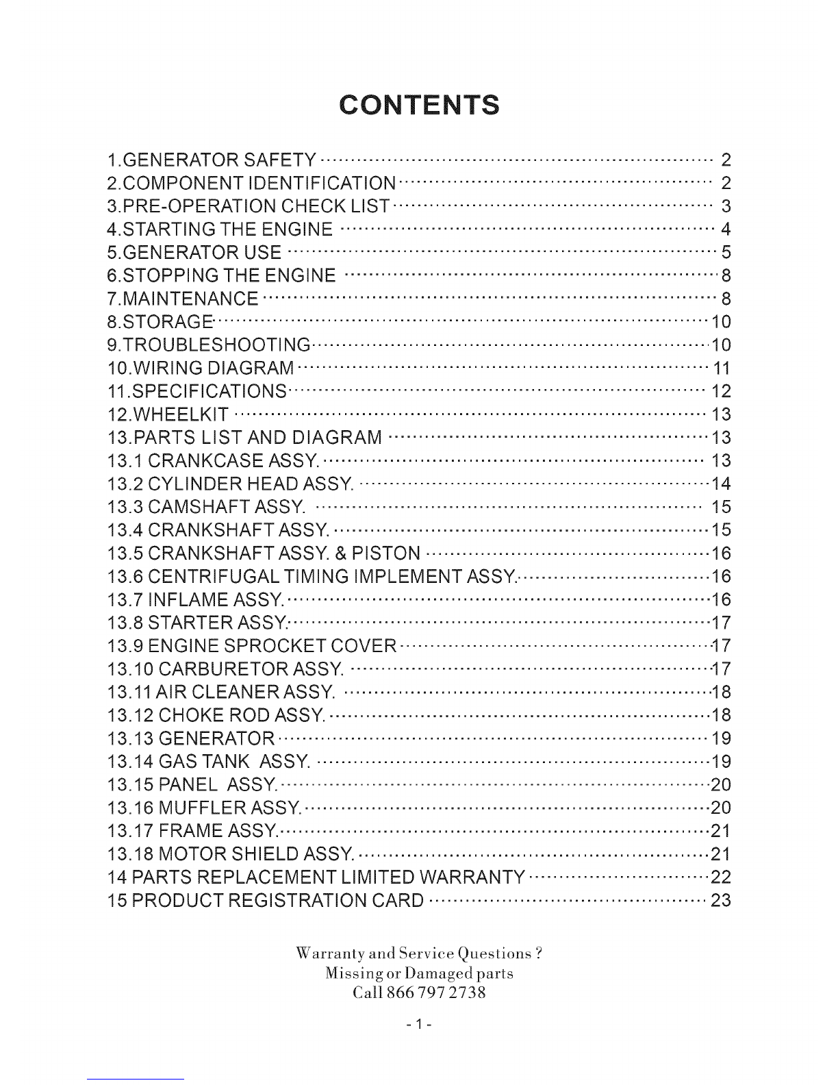
CONTENTS
1.GENERATOR SAFETY ................................................................. 2
2.COMPONENT IDENTIFICATION .................................................... 2
3.PRE-OPERATION CHECK LIST ..................................................... 3
4.STARTING THE ENGINE .............................................................. 4
5.GENERATOR USE ....................................................................... 5
6.STOPPING THE ENGINE .............................................................. 8
7.MAINTENANCE ........................................................................... 8
8.STORAGE .................................................................................. 10
9.TROU BLES HOOTI NG .................................................................. 10
10.WIRING DIAGRAM .................................................................... 11
11.SPECIFICATIONS ..................................................................... 12
12.WHEELKIT .............................................................................. 13
13.PARTS LIST AND DIAGRAM ..................................................... 13
13.1 CRANKCASE ASSY, •.............................................................. 13
13.2 CYLINDER HEAD ASSY. .......................................................... 14
13.3 CAMSHAFT ASSY. •............................................................... 15
13.4 CRANKSHAFT ASSY. .............................................................. 15
13.5 CRANKSHAFT ASSY. & PISTON ............................................... 16
13.6 CENTRIFUGAL TIMING IMPLEMENT ASSY.. ............................... 16
13.7 INFLAME ASSY,. ..................................................................... 16
13.8 STARTER ASSY. ...................................................................... 17
13.9 ENGINE SPROCKET COVER ................................................... .17
13.10 CARBURETOR ASSY. ............................................................ 17
13.11 AIR CLEANERASSY. •............................................................ 18
13.12 CHOKE ROD ASSY. •.............................................................. 18
13.13 GENERATOR ....................................................................... 19
13.14 GAS TANK ASSY. •................................................................ 19
13.15 PANEL ASSY.- ...................................................................... 20
13.16 MUFFLER ASSY. ................................................................... 20
13.17 FRAME ASSY.. ...................................................................... 21
13.18 MOTOR SHIELD ASSY. .......................................................... 21
14 PARTS REPLACEMENT LIMITED WARRANTY .............................. 22
15 PRODUCT REGISTRATION CARD .............................................. 23
Warranty anti Service Questions ?
Missing or Damaged parts
Call g66797 273g
-1-

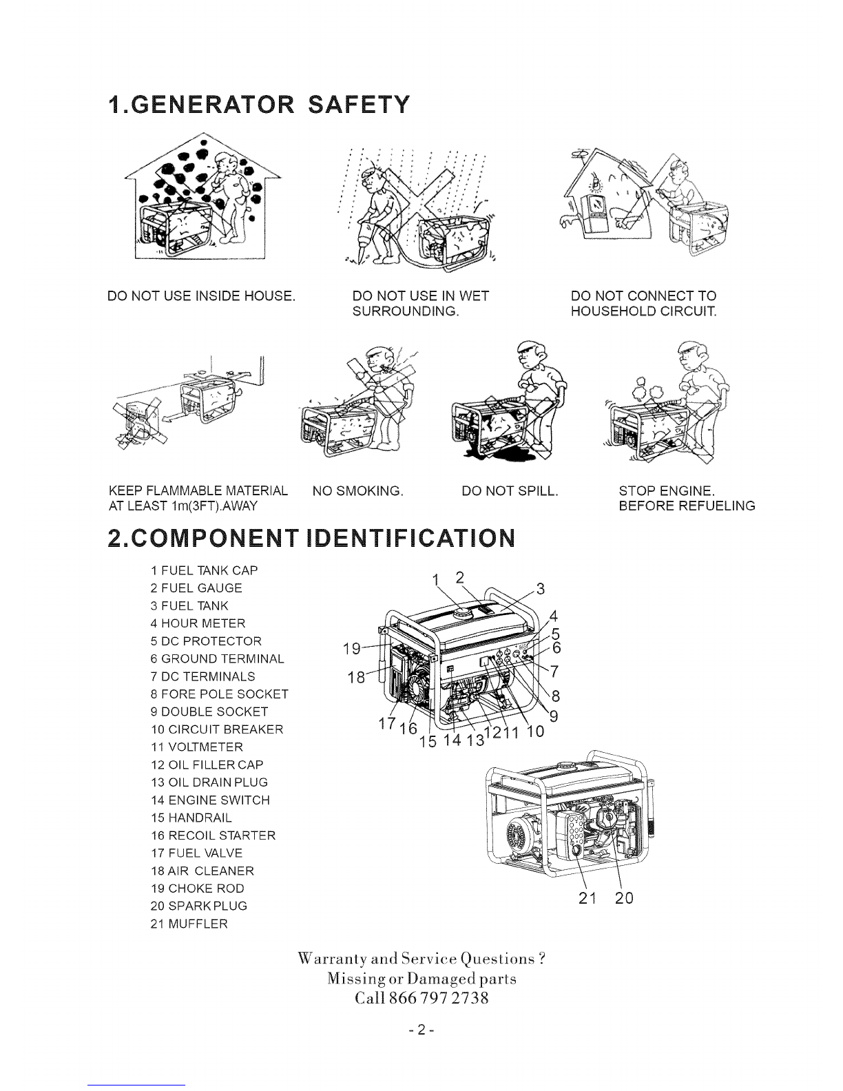
1.GENERATOR SAFETY
DO NOT USE INSIDE HOUSE.
/ii '
DO NOT USE IN WET
SURROUNDING.
%-
DO NOT CONNECT TO
HOUSEHOLD CIRCUIT.
KEEP FLAMMABLE MATERIAL
AT LEAST lm(3FT).AWAY
2.COMPONENT
1 FUEL TANK CAP
2 FUEL GAUGE
3 FUEL TANK
4 HOUR METER
5 DC PROTECTOR
6 GROUND TERMINAL
7 DC TERMINALS
8 FORE POLE SOCKET
9 DOUBLE SOCKET
10 CIRCUIT BREAKER
11 VOLTMETER
12 OIL FILLER CAP
13 OIL DRAIN PLUG
14 ENGINE SWITCH
15 HANDRAIL
16 RECOIL STARTER
17 FUEL VALVE
18 AIR CLEANER
19 CHOKE ROD
20 SPARK PLUG
21 MUFFLER
NO SMOKING. DO NOT SPILL.
iDENTiFiCATiON
1 2
1
1
171 0
15 14 13
21 20
STOP ENGINE.
BEFORE REFUELING
Warranty and Service Questions ?
Missing or Damaged parts
Call 866797 2738
-2-

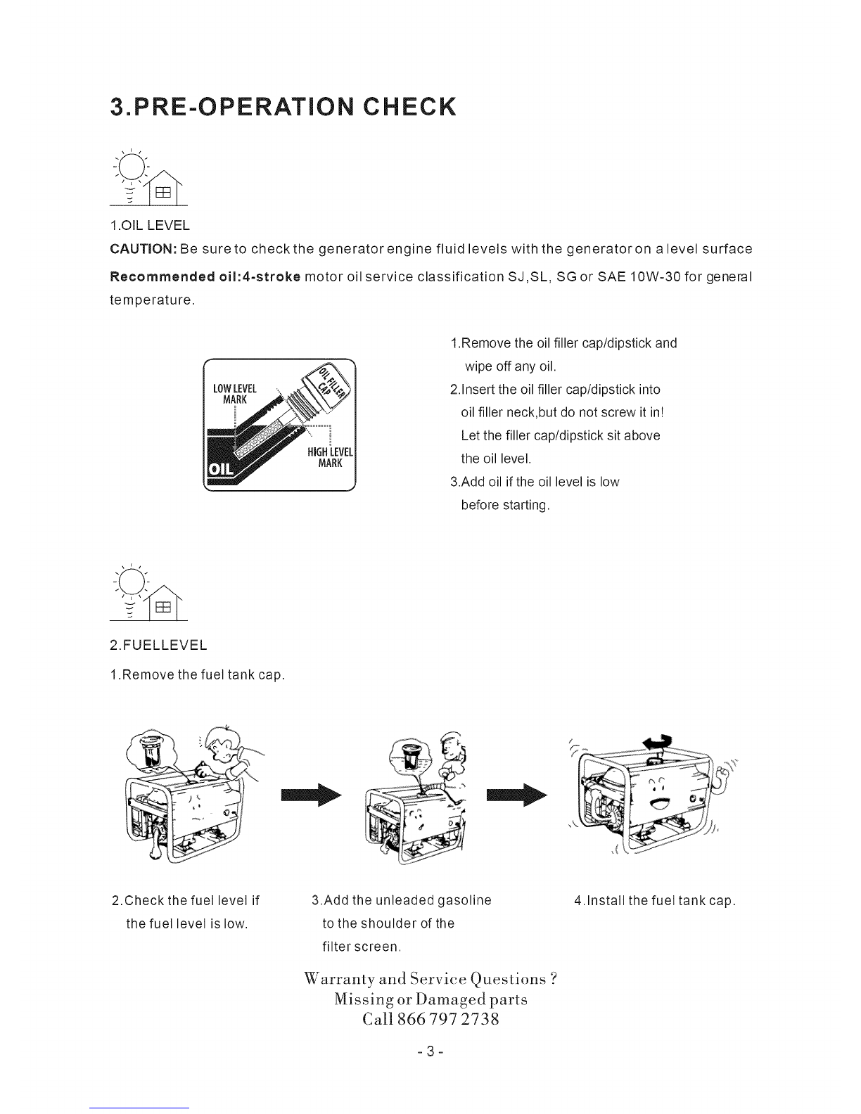
3.PRE-OPERATION CHECK
1.OIL LEVEL
CAUTION: Be sure to check the generator engine fluid levels with the generator on alevel surface
Recommended oil:4=stroke motor oil service classification SJ,SL, SG or SAE 10W-30 for general
temperature.
1.Remove the oil filler cap/dipstick and
wipe off any oil.
2.Insert the oil filler cap/dipstick into
oil filler neck,but do not screw it in!
Let the filler cap/dipstick sit above
the oil level.
3.Add oil if the oil level is low
before starting.
2.FUELLEVEL
1 Remove the fuel tank cap.
2.Checkthe fuel level if
the fuel level is low.
3.Add the unleaded gasoline
to the shoulder of the
filter screen.
Warranty and Service Questions ?
Missing or Damaged parts
Call 866797 2738
-3-
4. Install the fuel tank cap.

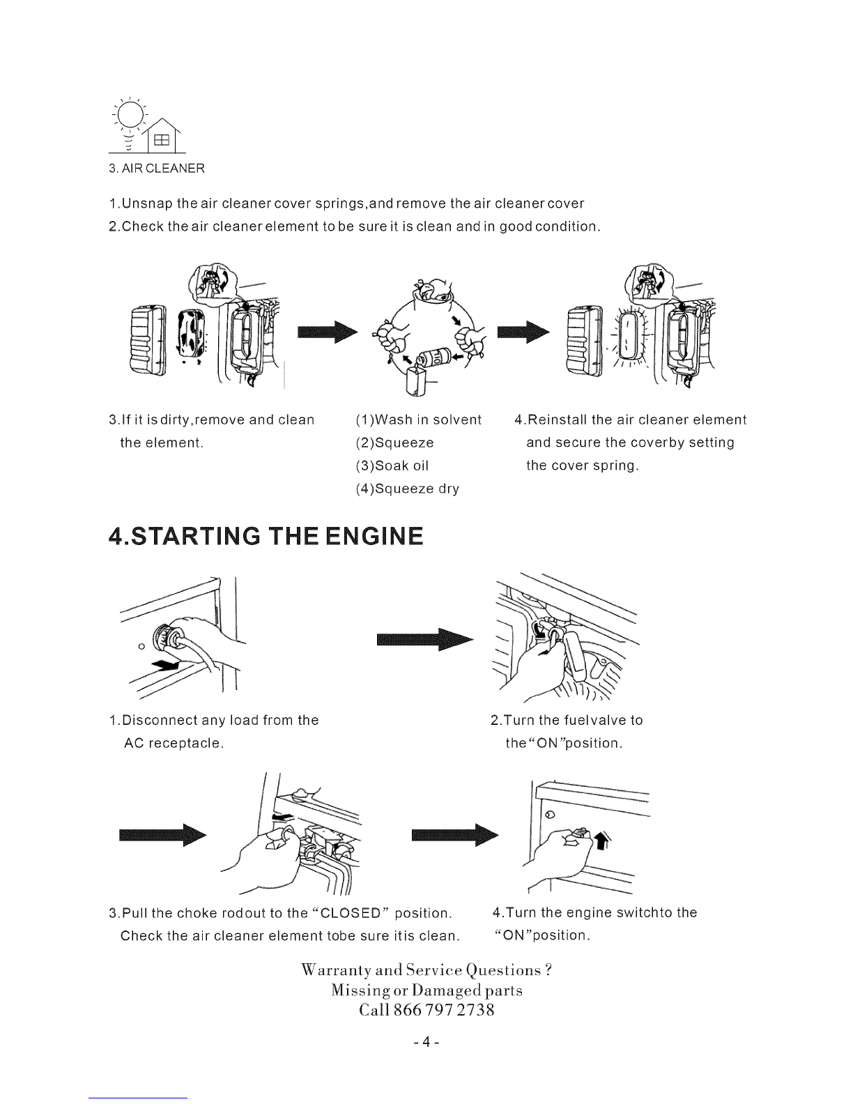
3.AIRCLEANER
1.Unsnaptheair cleanercoversprings,andremovetheaircleanercover
2.Checktheaircleanerelementtobesureit iscleanandingoodcondition.
3.Ifit isdirty,removeandclean
theelement. (1)Washin solvent
(2)Squeeze
(3)Soakoil
(4)Squeezedry
4.Reinstalltheair cleanerelement
andsecurethecoverbysetting
thecoverspring.
4.STARTING THE ENGINE
1.Disconnect any load from the
AC receptacle.
2.Turn the fuelvalve to
the "ON "position.
3.Pull the choke rodout to the "CLOSED" position.
Check the air cleaner element tobe sure itis clean.
4.Turn the engine switchto the
"ON'position.
Warranty and Service Questions ?
Missing or Damaged parts
Call 866797 2738
=4=

5.Pull the starter grip lightly until resistance is felt
then pull briskly.
Warning:Do not allow the starter grip to snap
back against the engine.
Return it gently.
J
6.Push the choke rod to the "OPEN" position
as the engine warms up.
5.GENERATOR USE
, To keep the generator always in top mechanical and electrical condition, observe the following:
1.To prevent electrical shock from faulty appliances, the generator _ ....... _:_
should be grounded.
Connect a copper wire to the generator and the other end of wit
to a metal stake driven into the ground. _,{_;
_
2.Combined load of the connected apparatus must not exceed the rated capacityof the generator
Electric apparatus, particularly motor-driven equipment, will draw a higher currentwhen starting. The
following table is provided for your reference when connecting such apparatus to your generator.
WATTAGE EXAMPLE
TYPE STARTING RATED STARTING RATED
E-o_
Ct,_
eU r5
O ©
jc::E
E
t"5
o
o
14-
E
o-
e>
O
Xl Xl
X2 X1.5
X3~5 X2
TYPICAL APPARATUS
incandescent lamp
@TV
Fluorescent lamp
"-_ efrigerator
Electric fan
APPARATUS
incandescent lamp
100W
40W
Fluorescent lamp
Refrigerator
_'_150W
100VA 100VA
(w) (w)
80VA 60VA
(w) (w)
450~750VA 300VA
(w) (w)
Warranty and Service Questions ?
Missing or Damaged parts
Call 866797 2738
=5=

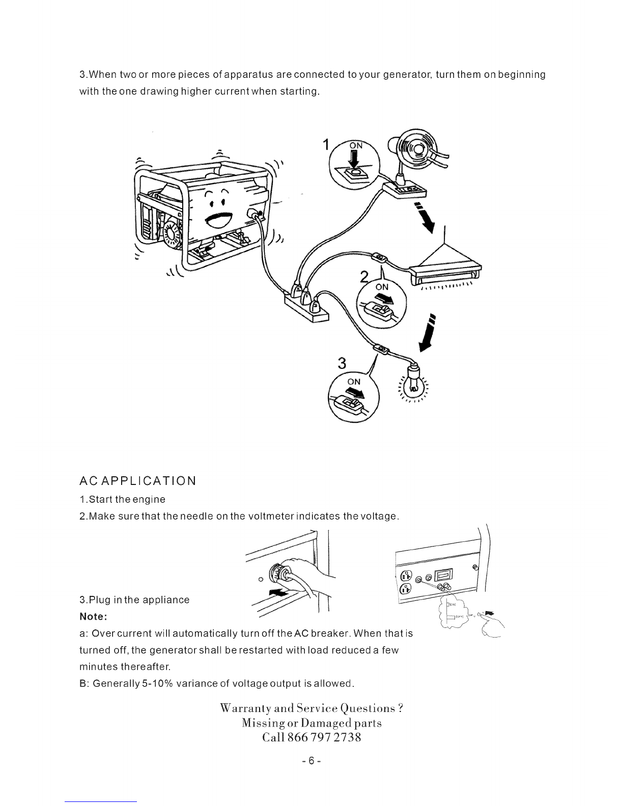
3.When twoor more pieces of apparatus are connected toyour generator, turn them on beginning
with the one drawing higher currentwhen starting.
ACAPPLICATION
1.Start the engine
2.Make sure that the needle on the voltmeter indicates the voltage.
o
3.PlUgNote:in the appliance thatis';_%'_
a: Over current will automatically turn off theAC breaker. When _.
turned off, the generatorshall be restarted with load reduced a few
minutes thereafter.
B: Generally 5-10% variance of voltage output is allowed.
Warranty and Service Questions ?
Missing or Damaged parts
Call 866797 2738
-6-

DC APPLICATION
The DCterminats may be used for charging 12V automotive-type batteries only
1.Connect the charging cables to the battery terminal.
2.Start the engine and charge the battery
NOTE:
An overloaded DC circuitwill trip the DCcircuit breaker
(push button comes out) If this happens.check the short
circuit or counter connection and wait a few minutes
before pushing the circuit protector.
3.Stop the engine,then disconnectthe
charging cables in the reverse orderof
connection.
(1) ON (2) OFF
6.STOPPING THE ENGINE
7:B/2_ p""
1.Turn off all electrical appliances. 2.Turn theengine switch
to the "OFF " position.
o
3.Disconnect the electrical 4.Turn thefuel valve to the
appliance. "OFF" position.
NOTE: To stop the engine in an emergency,turn the engine switch OFF.
Warranty and Service Questions '?
Missing o:r Damaged paris
Call 866797 2738
-7-

7.MAINTENANCE
(1):These itemsshoule be serviced bya dealer.
(2):Every 3 years
Check
Engine
oil
Air cleaner
0
I9
(_ Change Clean
First orm°nth Every 3ormonths
@
Every 6rn_Onths
(_) Check-Readjust
SEE page
EVeroYrYear
P.3
P.9
Fuel strainer @ P.9
Battery
fluid level (_
Spark plug @ P.9
ValveClearance ___ @(1) _
Combustion _ @(1)
Chamber
Fuel line I_ (_)
1.OIL CHANGE
1.Remove the oil filler cap.
2.Remove the drain plug and drain the oil.
3.Dispose of oil property.
4.Install the drain plug and tighten it securely.
5.Refill with the motor oil(see 3 page)and check the oil level
ENGINE OIL CAPACITY:37.2oz(1.1 Liter)
&Install the oil filler cap.
Recommended oil: 4-stroke motor oil service classification SJ,SL,SG or SAE 10W-30 for general
temperature.
Warranty and Service Questions ?
Missing or Damaged parts
Call 866797 2738
=8=

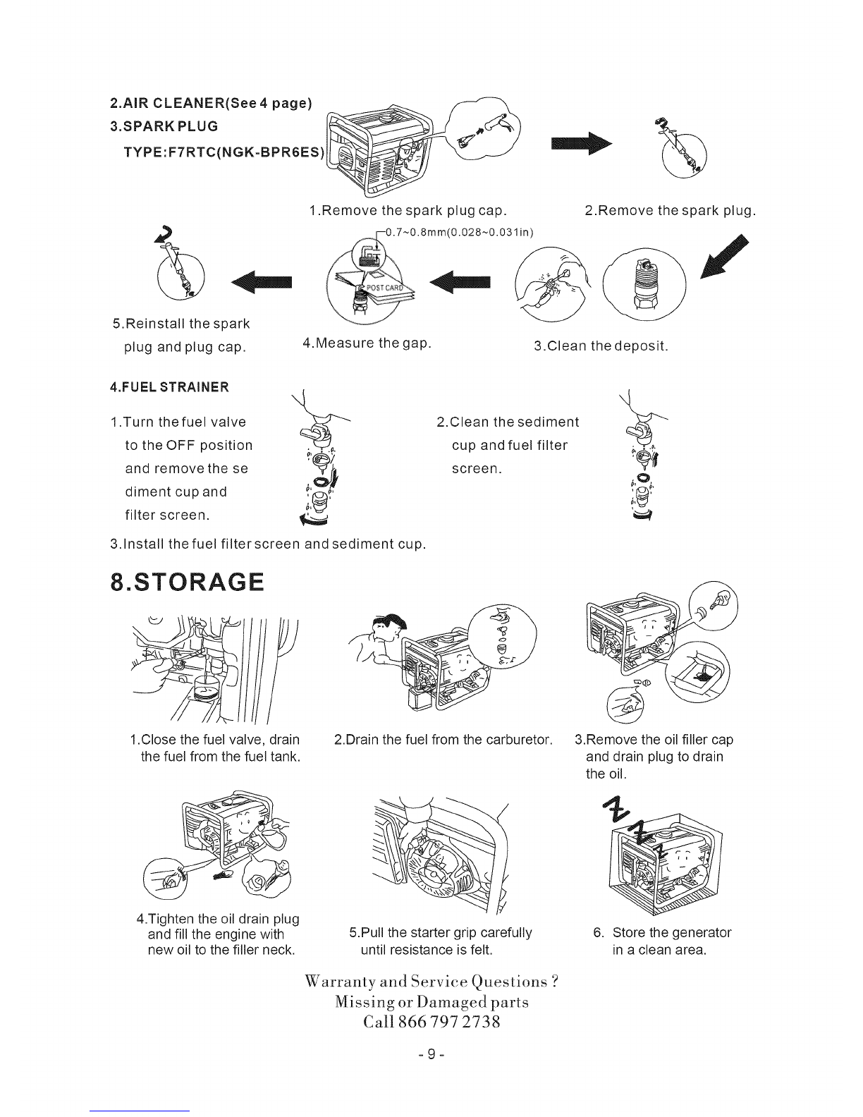
2.AIR CLEANER(See4 page)
3.SPARK PLUG
TYPE:FTRTC(NGK=BPR6ES)
%
5.Reinstall the spark
plug and plug cap.
1.Remove the spark plug cap.
(0.028~0.031in)
2.Remove the spark plug.
J
4.Measure the gap. 3.Clean the deposit.
4.FUEL STRAINER
1.Turn thefuel valve
to the OFF position
and remove the se
diment cup and
filter screen.
3.Install thefuel filter screen and sediment cup.
2.Clean the sediment
cup and fuel filter
screen.
8.STORAGE
1.Close the fuel valve, drain
the fuel from the fuel tank. 2.Drain the fuel from the carburetor.
4.Tighten the oil drain plug
and fill the engine with
new oil to the filler neck.
-.q
5.Pull the starter grip carefully
until resistance is felt.
Warranty and Service Questions ?
Missing or Damaged parts
Call 866797 2738
3.Remove the oil filler cap
and drain plug to drain
the oil.
6. Store the generator
in a clean area.
=9=
Autres manuels pour GG5500 Series
1
Table des matières
Autres manuels UST Générateur portable