
Usl CM Series Manuel utilisateur

CM SERIES
Monitor / Crossover
181 Bonetti Drive
San Luis Obispo, CA 93401
ph: 805-549-0161
fax: 805-549-0163
e-mail:[email protected]
Ten Channel

- 2 -
One Year Limited Warranty
USL, Inc. warrants that each product manufactured by it will be
free from defects in material and workmanship under normal usage
foraperiodofone(1)yearafteritspurchasenewfromanauthorized
dealer. Our obligation under this warranty is limited to repairing
or replacing any product or component which we are satisfied does
not conform with the foregoing warranty and which is returned to
our factory, freight paid, or serviced by one of our authorized
contractors. The forgoing warranty is exclusive and in lieu of all
other warranties, whether expressed or implied. Such warranty
shall not apply to any product or component (A) repaired or altered
by anyone other than USL, Inc. or an authorized service contractor;
(B) tampered with or altered in any way or subjected to misuse,
negligence or accident or (C) which has been improperly connected
installed or adjusted other than in accordance with USL, Inc.’s
instruction.

- 3 -
Table of Contents
Please record the following information for your records:
Model: ___________________ Serial Number: ___________
Date of Purchase: ________________
Purchased from: ____________________________________
Introduction .........................................................4
Front Panel Description........................................5
Rear Panel Description.........................................7
Installation............................................................9
Monitor and Bargraph Setup...............................13
Monitor and bargraph Levels..............................14
Specifications.....................................................15
Pinouts...............................................................17
- 4 -
Introduction
Please read this entire manual before commencing your
installation.
The Ultra Stereo CM Series Projection Booth Monitor has been
designed for high performance, ease of use, and years of trouble free
service. Installation and setup of the monitors has been
considerably simplified. No special tools are required. The built in
VU meter and test jack give the technician immediate information
about the status of the processor and all power amplifiers.
All controls necessary for daily operation of the processor are
easily accessible on the front panel. The components that make
up the CM Series monitors are of computer grade for reliability. All
front panel controls are individually sealed for long life. All
Ultra Stereo equipment has been “burned-in” at the factory for
an extended period in order to eliminate the possibility of
premature failure. Unpack the unit carefully. If the container has
been damaged, thoroughly inspect the equipment to make
certain that there is no hidden damage. File a claim immediately
with the carrier if any damage is found. Also advise your dealer
or the factory.
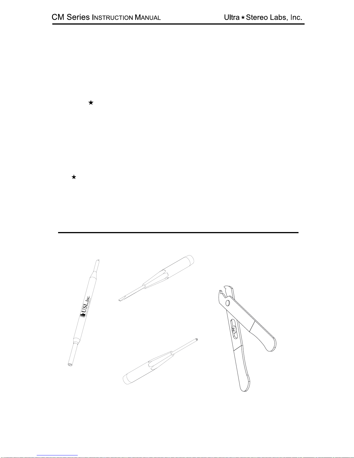
Small, standard
screwdriver
No. 2 Phillips
screwdriver
Trimpot
adjustment
tool Wire
Strippers
TOOLS REQUIRED

- 5 -
You will need to supply the following materials:
• Shielded audio cable for connecting the CM Series to the
cinema processor and power amplifier outputs.
• Four 10-32 x 1/2" screws to mount the CM Series in the audio
equipment rack.
FEATURES
The CM Series monitor has the following standard features:
• Ten-Channel Monitoring - allows you to monitor either the
processor or power amplifier outputs to left, left center, center,
right center, right,surround left, surround right, back surround
left, back surround right and subwoofer channels, in any
combination via the switches on the front panel (see illustration
on pg. 5)
• Input levels from processor and power amplifier can be
adjusted independently - no huge level jumps when switching
between processor and power amplifiers.
• Bargraph display may be calibrated to the reference level
for your theatre – the projectionist can see auditorium levels
instantly.
• Designed to work with bi or tri-amplified sound systems to
monitor the high, mid and low frequency outputs from the left,
left center*, center, right center* and right channels.
• Line output for remote monitoring with an external amplifier
and speaker.
*Left center, right center only available with installation of optional
card.

- 6 -
1. Channel select buttons - pressing a Channel Select Button causes the corresponding LED to illuminate
and the signal from that channel to be monitored. Any combination of ten channels can be selected.
2. Internal Digital or Analog Crossover Access Cover.
3. Crossover Bypass Switch - Switching this will cause the internal crossover to be bypassed or engaged
and the condition will be indicated by its appropriate LED.
4. Volume Control - controls the volume of the internal speaker and test jack (7). The volume control
has no effect on the VU Bargraph display.
5. Processor/Amplifier Selector Switch - selects either the inputs from the cinema processor or power
amplifiers for monitoring.
6. VU Bargraph - displays the level of the selected channels. The VU Bargraph may be calibrated by
the rear panel trim adjustment (Figure 2). The VU Bargraph operates independently of the volume
control (4).
7. Test Jack - permits monitoring of the audio output of the CM Series. Inserting a mono or stereo 1/4”
phone plug here disables the internal speaker and routes the audio output to the Test Jack. Do
not connect any device here with less than 8 Ohms impedance.
8. Internal Speaker
9. Power Switch
1234567 8 9

- 7 -
1. Main AC connector with fuse.
2. Inputs from Amplifier outputs - connect to the
power amplifier speaker outputs corresponding to
Lh, Lm, Ll, Ch, Cm, Cl, Rh, Rm & Rl channels and
COM.
3. Inputs from Amplifier outputs - connect to the
power amplifier speaker outputs corresponding to
Lch, Lcm, Lcl, Rch, Rcm, Rcl, SW+, SW- channels,
COM and Chassis ground.
4. Amplifier level - this trimpot adjusts the sensitivity
of the front panel Bargraph meter and Line Out
when in Amplifier mode.
2 3 4 5 6 7 8 9 11 12 13 14 212017 18 1910 16151 22 23 24 25 26
15. HD-15 connector - connect to Rl amplifier.
16. HD-15 connector - connect to RM*/h amplifier.
17. HD-15 connector - connect to Cl amplifier.
18. HD-15 connector - connect to Cm*/h amplifier.
19. Crossover outputs - connect to the power amplifier
inputs corresponding to Lh+, Lh-, Lm+*, Lh-*, Ll+, Ll-,
Ch+, Ch-, Cm+*, Cm-*, Cl+ & Cl- channels.
20. HD-15 connector - connect to Ll amplifier.
27
115V
230V

- 8 -
5. Pins 1-4: Inputs fromAmplifier outputs - connect to
the power amplifier speaker outputs corresponding to
Ls, Rs, Bsl & Bsr.
Pins 5-8: Crossover outputs - connect to the power
amplifier inputs corresponding to Bsl+, Bsl-, Bsr+, Bsr-
channels, Ground and Line Out. Note: Line Out level
is affected by Amplifier level (4) and Processor level
(22)
6. HD-15 connector - connect to SW amplifier.
7. HD-15 connector - connect to Bsl/Bsr amplifier.
8. HD-15 connector - connect to Ls/Rs amplifier.
9. Crossover outputs - connect to the power amplifier
inputs corresponding to Rch+, Rch-, Rcm+, Rcm-,
Rcl+, Rcl- Ls+, Ls-, Rs+, Rs-, SW+ & SW- channels.
10. HD-15 connector - connect to Rcl amplifer
11. HD-15 connector - connect to Rcm*/h amplifier.
12. HD-15 connector - connect to Lc amplifier.
13. HD-15 connector - connect to Lcm*/h amplifier.
14. Crossover outputs - connect to the power amplifier
inputs corresponding to Rh+, Rh-, Rm+, Rm-,Rl+, Rl,
Lch+, Lch-, Lcm+, Lcm-, Lcl+ & Lcl- channels.
21. HD-15 connector - connect to Lm*/h amplifier.
22. Processor level - this trimpot adjusts the sensitivity
of the front panel Bargraph meter and Line Out when in
Processor mode.
23. Bargraph level - this trimpot adjusts the sensitivity
of the front panel VU Bargraph.
24. Main input - connect this to the main outputs of the
processor.
25. AC Emergency power input - 12-16VAC, 0.5A
26. Channel configuration DIP switches. See page 15.
27. Optional input - connect these to the EX outputs of
the processor.
* - When used in Biamp mode, Mid band becomes
the Low band output

- 9 -
Installation
Mount the CM SERIES MONITOR
The ideal place for the CM Series Monitor is in the sound rack or
projector console between the stereo processor and power amplifiers. DB25
and HD15 connectors are available on the back plane to make installation
quick and easy. Alternatively, terminal blocks allow the use of stripped and
tinned wire. They are pluggable for easy service and trouble shooting.
Monitor Hookup
1. Power: Connect the unit to the AC power outlet using the standard IEC
cable provided.Any power source from 100-300VAC, 50-60 Hz will be sufficient.
Plug the Modular Power Supply into the Bypass Power input and power source
matching the Modular Power Supply requirements.
2. Monitor Inputs From Processor Outputs: Use the male-female 25 pin D
cable to connect the output of the cinema processor to the Main input of the
CM Series. If “EX” channels are to be used, then plug an additional male-
female 25 pin D cable from the “Optional Outputs” at the processor to the
“Optional Inputs” of the CM Series
3.Crossover Outputs to Power Amplifier Inputs: The CM Series utilizes HD15
connectors that mate with several popular amplifiers. Plug one end of the
“VGA” HD15 cable into the chassis connector on the rear of the CM Series.
Plug the other end of the cable into the appropriate amplifier. The VGA cable
not only carries the CM Series crossover signal to the amplifiers, but also
carries a power amp output signal back to the CM Series monitor.
Terminal blocks are also provided on the back of the CM Series chassis to
allow wiring to traditional amplifiers without the HD15 interface. All crossover
outputs are balanced. Please use two conductor shielded cable to minimize
ground loops and hum. Connect each of the crossover channel outputs to the
appropriate amplifier inputs.
4. Monitor Inputs From PowerAmplifier Outputs: When VGA cables are NOT
being used, the amplifier outputs must be connected to terminal blocks 2 &
3. Unshielded wire can be used to connect the output of the amplifiers to the
appropriate monitor speaker.
Inputs on the rear panel of the CM Series: All of these inputs are unbalanced
except for the subwoofer.

- 10 -
Left
High/Mid
Amplifier
Input
Left
Low/Spare
Amplifier
Input
Typical CM Series Triamp
Terminal Wiring
Typical CM Series Triamp
Amplifier Input Connection
115V
230V
Left Low/Spare
Amplifier
Output
L R Left High/Mid
Amplifier
Output
L R
Autres manuels pour CM Series
1
Table des matières
Autres manuels Usl Crossover


