Unitek BAMO A1 Manuel utilisateur

BAMO
MANUAL
Batterie - Motor-Controller
BAMO A1, A2-x-60 ... 500
for DC-Motors
Ausgabe
1108-1

2
BAMO A1, A2 60-500A
Contents
1 Basical Information Page
Safety Advice 3
General Information 4
Application 4
Construction 4
Technical Data 5
2 Mechanical Installation
Dimensions 60, 120, 240 6
Dimensions 280 7
Dimensions add. Heatsink 60 … 240 8
Dimensions add. Heatsink 280 9
3 Electrical Installation
Connection Overview 10
Power connections 11
Control connections 12
Speed-command value 13
External current limit 14
ready for operation (BTB) indication 15
Analogue maesuring outputs 15
Plug-Clamp Numbers 16
4 Device Overview
Component overview 17
Blockdiagram 18
Adjustment functions 19
5 Adjustment
Adjustment advice 20
Speed - command value 21
Speed - actual value 22
Current limitation 23
Speed controller switching 24
Adjustment without measuring instruments 24
6 Getting Started
Default setup 26
First getting started 27
7 Fault Finding
Functions errors 28
Signals 29
8 Protocol 30
9 Guarantee 31
Contents

1 Basic - Information
BAMO A1, A2 60-500 3
Electronic devices always involve the risk of failure.
This manual has to be read carefully and must be understood by experts before installing
or starting the device.
If there are any doubts call your trader or the manufacturer.
The BAMO series is designed to regulate electrical currents;
protection standard IP00.
Connection only to a battery or galvanic isolated direct voltage. (See Page 10)
Standards and Guidelines:
The device and it’s associated components can only be installed and switched on where
the local laws and technical standards have been strictly adhered to:
EU-Guidelines 89/392/EWG, 84/528/EWG, 86/663/EWG, 72/23/EWG
EN60204, EN50178, EN60439-1, EN60146, EN61800-3
- IEC/UL IEC364, IEC 664, UL508C, UL840
- VDE-regulations VDE100, VDE110, VDE160
- TÜV-regulations
- Regulations of Professional and Occupational bodies: VGB4
The user has to assure that: after
- a failure of the device
- an incorrect handling
- a failure of the control unit etc.
the drive is brought to a secure operating condition.
Machines and installations are to be provided with supervisory and safety equipment,
that is independent of the device.
Adjustment
-only by qualified personnel
- adher to safety regulations
Installation work
-only when disconnected from all power lines.
QS
The devices are archived by the manufacturer with serial number and their test
specifications.
CE
The EU-guide line 89/336/EWG with the Regulations EN61000-2 and EN61000-4 are
observed.
Caution Direct Voltage
DC 160V=
Safety advice

4
BAMO A1, A2 60-500A
General Information
The battery motor controller BAMO-Ax-xx forms together with the low voltage DC-motor a
propulsion unit distingushed by its high control range.
With a DC-motor the current is proportional to the torque and the voltage is proportional
to the speed.
Current and voltage are measured precisely.
The analogue circuits of the servo driveare simply constructed.
The speed actual value is generated from armature voltage or from the
DC-tachogenerator.
The speed and the current controller are disigned as P-I-controller.
In version BAMO-A2 (4Q) the brake energy is refeeded to the battery.
Application
for all kinds of machines or vehicles up to 40kW battery feeded drive power
especially for
- a great controller range
- a high efficiency
- small motor dimensions
- a even and smooth travel
for speed or torque regulation or
combined speed-torque regulation with or without superposed position controller.
For use in
battery powered vehicles like cleaning machines, el. boats,
fork-lift trucks, transport systems,
Solar- or wind powered installations,
and many other battery powered machines and installations.
Construction:
Cubicle-mount unit in IP00 according to the VDE- DIN- and EU- regulations.
Standard analogue regulation electronics.
Power electronics with IGBT-power semiconductors,generous dimensioning.
Characteristics:
* Battery supply or galvanicisolated direct voltage (Notice advice on page 10 !)
* Galvanic isolation between auxiliary voltage and regulation electronics
auxiliary voltage and power stage
regulation electronics and power stage
* Differential command value inputs
* Speed and torque regulation
* Static and dynamic current limit
* Measuringoutputs for speed and current
* Enable logic, quick stop
* Temperature control for motor and device
General Information
1 Basic - Information
BAMO A1, A2 60-500 5
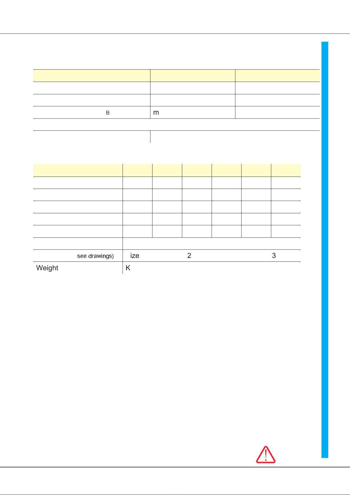
Technical Data
Power Connection
Type BAMO A1, A2 36 - 60 … 360 160 - 60 … 360
Battery voltage 12, 24V 36 up to 160V
Direct voltage bus 12, 24V 36 up to 160V
Output voltage 0.8 x U
B
max.30V max. 150V
Auxiliary voltage 24V= ±20%, max. 0.5A, waviness <20%
Spezifications
Common specifications
Protection standard IP 00
Device layout VDE 0100 group C
VDE 0160
Humidity stress class F accordig to DIN 40040
no dewing
Set up height < 1000m above NN
Operation range 0 ... 45°C
Extended operation range up to 60°C red. 2%/°C
Bearing range -30°C up to + 80°C
Speed controller
control accuracy without actual value error ± 0,5%
Control range 1: ,000
Temperature observation 80°C
VERSIONS: BAMO A1-xx1 Quadrant-controller propeling in rotation direction
BAMO A2-xx4 Quadrant-controller propeling and breaking in both
rotation directions. Energy rear feed
CAUTION: for battery operation or direct current bus only
(see advice on page 10)
Technical data
Type BAMO A1, A2 -x-60 120 180 280 360
Steady current max. A= 60 120 180 280 360
Peek current max. (5s) A= 100 200 300 400 600
El. power max kW 7.8 15.6 23.4 36.4 46.8
Power dissipation W 300 600 900 1400 1800
External fusing A 80 160 300 500 600
Cooling See cooling advice page 8
Dimensions (
see drawings)
Size 2 3
Weight Kg 6 11

6
BAMO A1, A2 60-500A
Dimensions BAMO A1,A2-x-60,120,240
Size 2
Mounting plate or
additional head sink .
(error)
Dimensions

BAMO A1, A2 60-500 7
2 Mechanical installation
Dimensions BAMO A1, A2-x-280, (500)
Size 3
Dimensions
Mounting plate or additional head sink.

8
BAMO A1, A2 60-500A
Additional heat sink type LUKUE - 3,4 (mountig on the BAMO)
Heat sink
Size 2 1x addit. heat sink LUKUE 3 (Weight + 3kg)
Size 3 1x addit. heat sink LUKUE 4
or 2x LUKUE 3 (Weight + 6kg)
Screws M10x110mm

BAMO A1, A2 60-500 9
2 Mechanical installation

10
BAMO A1, A2 60-500A
EnableEnable
Comm.value
potentiometer
PLC-
comm.value
Case
Comm.value±
Speed-act.value
Current-act.value
Current-comm.value
S1 contact 1
BTB
BTB
signal
Current limit
external
Overload-
signal
TERMINAL X3
Enable
Comm.value ±
Battery voltage
Motor connection
Case
Auxiliary voltage 24V=
X2:
X1: BAMO A1, A2
Notice:
Power connection X3:2 (-UB) , X3:10 (+UB)
Connection polarity > no protection against mixing up the contacts
when the connection is wrong the output stage can be
distroyed!
The power connection must not be devided during braking! If nessesary built in
reverse-current-protection-diode D1. On-stage current = device peek current
Connection to Direct voltage bus or Power supply unit
Make sure that the overvoltage in the buffer circuit is limitated to 20% during braking.
Small resistance of the source or ballast circuit.
If the resistance of the motor is very small the fast rising of the buffer voltage circuit can
demage the semi-conductors. In normal case the device is switched to error by the
overvoltage observation.
Auxiliary voltage connection X3:13, X3:14
Safe against mixing up the contacts. The connection can be switched seperated
from the power connection.
Notice the tolerance and the residual ripple of the voltage.
Motor connection X3:4 (M1),X3:8 (M3)
The motor connections can be exchanged.
In case of EMC-problems use chokes and shielded line.
Brakong resistor RB1 and DC-contactor K1 as resistor brake with type A1 or as battery
failure brake with type A2
Control connections see special advices.
Connection overview
Ce manuel convient aux modèles suivants
1
Table des matières
Autres manuels Unitek Contrôleurs


