UBTECH Jimu Manuel utilisateur

APP Instructions

A.Components Introduction
Controller------------------------------------------------------------------------------------------------------------------1
Battery--------------------------------------------------------------------------------------------------------------------2
Servos---------------------------------------------------------------------------------------------------------------------3
Connectors---------------------------------------------------------------------------------------------------------------5
Decorating Pieces--------------------------------------------------------------------------------------------------------5
Power Switch------------------------------------------------------------------------------------------------------------6
Decorating Piece - Fasteners-----------------------------------------------------------------------------------------6
Connecting Cables-------------------------------------------------------------------------------------------------------7
Assembly Tool------------------------------------------------------------------------------------------------------------7
B.Assembly Introduction
Key Parts-----------------------------------------------------------------------------------------------------------------8
Assembly Methods-----------------------------------------------------------------------------------------------------10
C.Jimu APP
Getting the Jimu App-------------------------------------------------------------------------------------------------11
Using Ubtech Account to Log in-------------------------------------------------------------------------------------11
D.Learn to Build
Tutorial-------------------------------------------------------------------------------------------------------------------12
Ocial Models----------------------------------------------------------------------------------------------------------12
E.Wireless Connection
Wireless Connection Process and Connection Requirements--------------------------------------------------14
F.Remote Control----------------------------------------------------------------------------17
G.Movement Introduction
Creating Movements--------------------------------------------------------------------------------------------------19
Movement Principle---------------------------------------------------------------------------------------------------19
Creating Movements-------------------------------------------------------------------------------------------------20
H.Creating
Selecting Category----------------------------------------------------------------------------------------------------23
Adding Photos---------------------------------------------------------------------------------------------------------23
Naming------------------------------------------------------------------------------------------------------------------23
I.Sharing and Discovery----------------------------------------------------------24
J.FAQ----------------------------------------------------------------------------------------------------25

The brain of a Jimu robot is a Main control box. Once the mobile phone has connected over
wireless to the main control box, it can be used to control the Jimu robot. There is an exclusive
MAC address for the controller on its back. The Main control box has slots, plugs and ports,
which allows the robot be assembled by splicing, integrating, and connecting.
Note:
For more information about ports , please refer to:
Assembly Introduction - Connections
Motherboard Specifications
Processor - STM32F070
Memory - 4M
Communication - dual-mode Bluetooth 3.0/4.0 BLE+EDR
1.Main Control Box
Battery
Power Indicator
Located on the left side of the main control box, it
indicates the current power status of the main control
box. Statuses as displayed by the indicator are as follows:
Red = charging
Green = fully charged
Flashing green = operating
Charging Interface
Used to charge the controller
4-Pin Cable Connector
For connecting the 4-pin sensors
3-Pin Cable Connector
For connecting the 3-pin servos or sensors
External LED Interface
For connecting external LED
Power Switching Interface
For connecting the power switch
Components Introduction
1
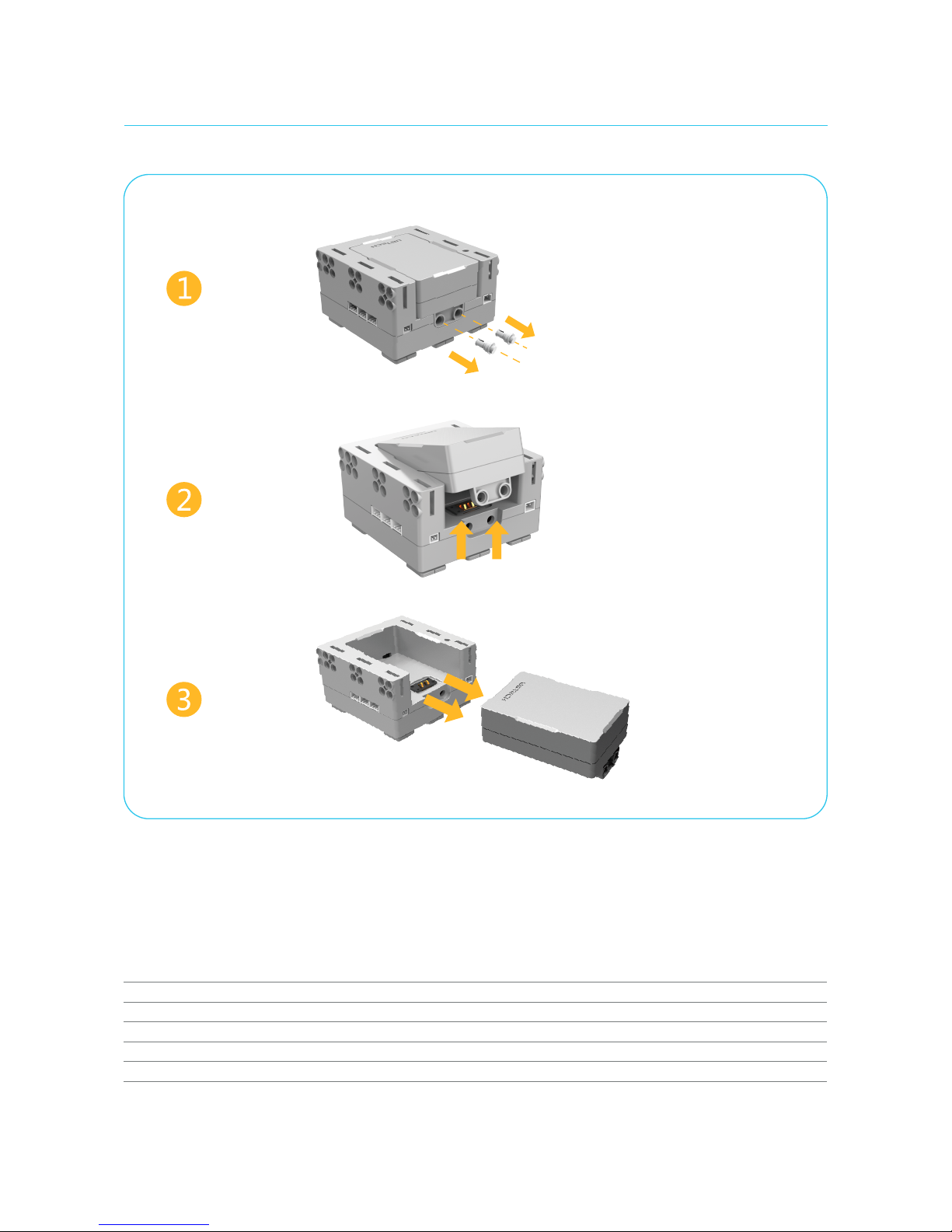
The battery comes factory-installed on the main control box. You can also replace the battery. Remove the plugs
on the downside before disassembling the battery from the main control box. Install the replacement battery into
the controller and then secure the plugs.
Detaching the Battery
2.Battery
Battery Specifications
Operating voltage: DC 6.5 - 9.6 V
Operating current: 1 - 2 A
Battery capacity: 1,200 mAh
Battery parameter: Lithium polymer battery
Operating temperature: 23 - 113 °F (-5 - 45 °C)
Remove the plugs
Gently lift up the battery
Remove the battery
2

Servo ID
Each servo has an ID number to distinguish it from the other servos. Please see "Connecting Model - Changing Servo ID" for more details.
Slots
There are 5 slots on the servo with which the rudder can be spliced, namely "ABCDE". For more details, please see: "Assembly Introduction - Splicing".
Servos are like human joints. They are the keys for the Jimu robot to perform movements.
Servo external view
Servo ID
3.Servos
3

Servo Rotation Modes
There are two dierent rudder rotation modes.
In the normal mode, the rotation range of the rudder is between -120° to 120°. And the time range for it to rotate from one angle to another is
80ms - 5,000 ms. In the wheel mode, the rudder can rotate 360° clockwise or counterclockwise. The rotation speed can be set to "Very slow", "Slow",
"Normal", "Fast", and "Very fast".
3-Pin Ports
Energy and information can be transmitted between the Main control box and servos. The 3-pin cable can be used to connect controller and
servo, or servo and servo 3-pin ports.
Rotatable Rudders
The rudders of the servo can rotate, and it can also be spliced with slots. "△□☆○" indicates dierent splicing directions. When "△" is aligned with the
scale, the angle of the rotatable rudder is 0°. For more information regarding the use of servo rudders and other components assembly, please see:
"Assembly Introduction: Splicing".
When "△" is aligned with
the scale, the angle of the
rudder is 0°.
Servo Technical Specifications
Output torque: 4 kg.cm
Operating voltage: 6.5 - 9.6 V
Operating current: 80 - 200 mA
Stall current: 1,700 mA
Rotation speed: 0.1 sec/60°
Accuracy: idle 1/3°, loaded 1°
Rotating 360°clockwise;
4
3-Pin
Ports
Rotating 360°counterclockwise.

Connectors are the skeleton of the robot. Slots or rudders of connectors can be spliced together
with other components' rudders or slots.
Example:
Connecting Servo with C3
4.Connectors
Decorating pieces can also be integrated with other components through plugs and attachments.
The decorating pieces are the cover of the model and give it a more attractive appearance.
5.Decorating Pieces
Straighten the rudder and
align the component.
Push the right side of the
component as indicated by
the arrow, until you hear a
popping noise.
Adjust the other side. When
you hear the same popping
noise, the component has been
successfully installed.
Pop
Pop
Gently widen both sides
of the component.
5

Power allows the Jimu robot to operate. Use the connecting cable to connect the
power switch to the Main control box. Turn on/othe power using the power switch.
6.Power Switch
Note: Fasteners come in dierent shapes, lengths and sizes.
Fasteners can integrate decorating pieces, connectors, the
controller, and servos together through holes.
7.Decorating Piece - Fasteners
6

Connecting cables are like blood vessels of the Jimu robot. It can connect the controller
with servos, and a servo with another servo. It can also transmit energy and commands
between the controller and servos.
The assembly tool can help you install and remove components, making the building process of your
model simpler and easier.
The end of the assembly tool is a clip. It can clip onto connectors to remove them from the components, or install them into the components.
8.Connecting Cables
Use method
9.Assembly Tool
7

1.Key Parts
a. Slots:
c. Plugs: Plugs on components come in dierent shapes and sizes, and are compatible with dierent fasteners.
b. Rudders: Rudders are rectangular structures projecting from components. The symbols "△□☆○" are used to indicate the
dierent directions.
Assembly Introduction
8
圆孔位
十字孔位
The slot is a groove in components, which usually appears on connectors and servos. When a component has multiple slots,
the "ABCDE" naming method will be used to distinguish them.
Table des matières
Autres manuels UBTECH Robotique


Manuels Robotique populaires d'autres marques

STEMCenter USA
STEMCenter USA Pi-Bot v2.00 Manuel utilisateur

SunFounder
SunFounder PiDog Manuel utilisateur

Universal Robots
Universal Robots UR5 Manuel utilisateur

Universal Robots
Universal Robots E Series Manuel utilisateur

YASKAWA
YASKAWA MOTOMAN-MPL80 II Manuel utilisateur

EFORT
EFORT ECR5 Manuel d'instructions


