Tycon Power Systems RemotePro RPSTL24 Manuel utilisateur

RPSTL12/24/48M
RemotePro®
Remote Power System
▫Wireless Base Stations
and Client Devices
▫Surveillance Cameras
▫Remote Sensors
▫Remote Lighting
▫Off Grid Electronics
Congratulations! on your purchase of the RemotePro® off-grid
remote power system. Please take a moment to review this Qwik
Install Guide before assembly or battery installation. Other in-
structions come with other components of this kit. Be sure to re-
view all instructions.
DANGER! Voltages in this system can exceed
65VDC and are very dangerous!
You Can Be Killed!
When following the instructions in this guide take extreme care to avoid
contact with output of solar panels. Only licensed electricians or those
with experience working around high voltage should attempt to install.
Safety: For your own protection, follow these safety rules.
▫Perform as many functions as possible on the ground
▫Do not attempt to install on a rainy, windy or snowy day or if
there is ice or snow accumulation at the install site or if the
site is wet.
▫Make sure there are no people, pets, etc. below when you are
working on a roof or ladder.
Recommended Tools: Phillips & Flat Screwdriver, 17/13/10mm
wrench, 8mm nut driver
Please help preserve the environment and return
used batteries to an authorized depot. Most auto
parts stores will pay for your used battery.
2
Qwik Install
STEP 0: Install mounting pole per separate instructions.
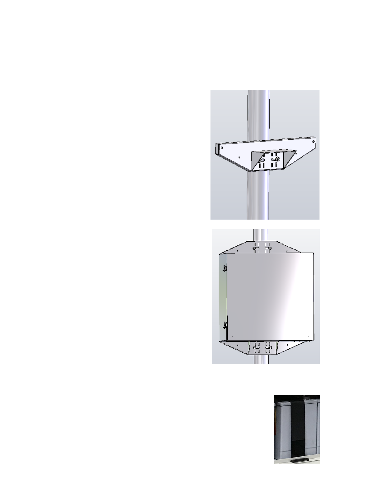
STEP 1: Prepare the enclosure: Install DIN rail (if required) to door
using two phillips head screws. Install just the top mounting bracket to
the enclosure using two 8mm bolts.
NOTE: It takes two people to mount the
enclosure to a pole. The standard U-Bolt
mounting accommodates a pole up to 4”
diameter. Multiple pole straps can be
used for extra strength. Pole straps are
available for poles up to 11” diameter or
larger.
STEP 2: Install the bottom bracket and
stabilizer bracket to the pole using U-Bolt
and Pole Straps. The stabilizer bracket is
used as an aid to mounting and addition-
al support when mounted.
STEP 3: Lift the enclosure and place it
on the stabilizer bracket. Connect the top
bracket to the pole using U-Bolt and/or
Pole Straps.
STEP 4: Attach the two 8mm bolts that
hold the bottom bracket to the enclosure.
Make sure all bolts are tight. (8-15 ft lbs)
STEP 5: Install the three wire feedthru
cable glands in the holes in the bottom of
the enclosure. If one or more of the cable
glands will not be used, just cut a short
piece of cable and tighten in the cable
gland to seal it.
NOTE: The bottom plate can be removed
from the enclosure if you need to add
some additional feedthru. (ex; conduit
connection)
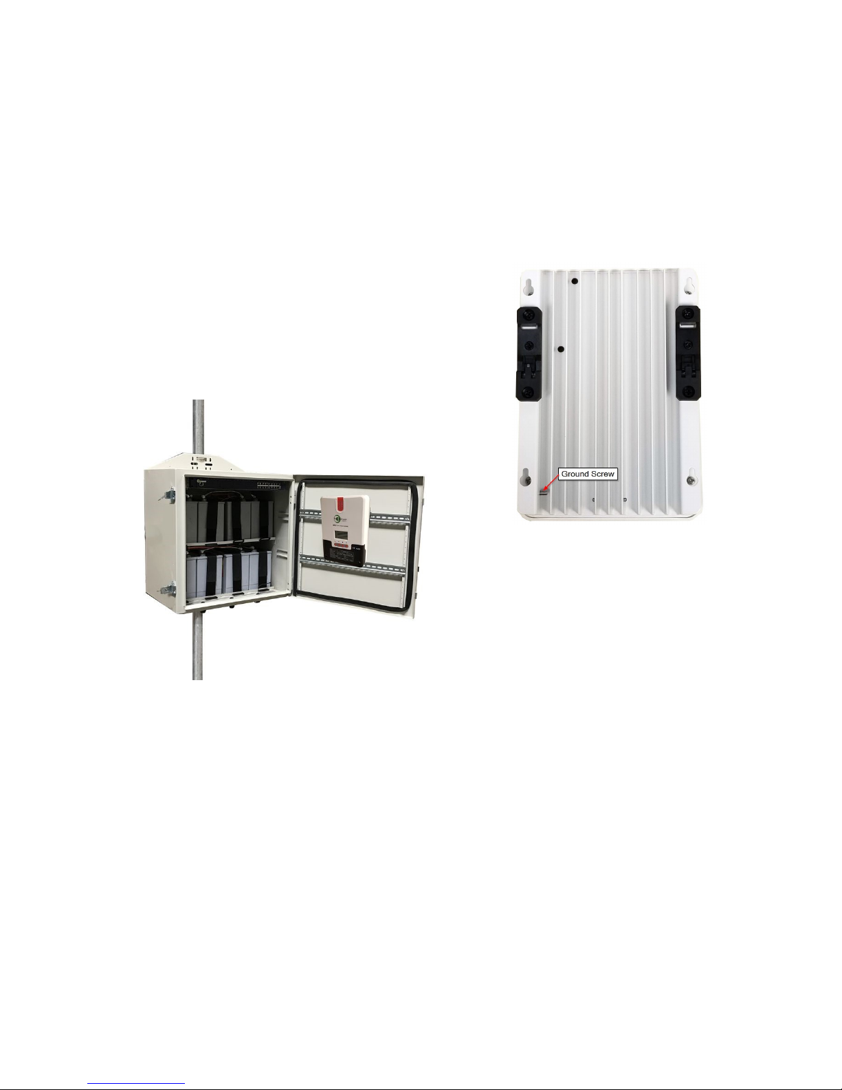
STEP 6: Install the batteries in the enclosure. For 12VDC the batteries
are connected in parallel, for 24VDC the batteries are con-
nected in series pairs and for 48VDC the batteries are con-
nected in series. (See wiring diagrams later in this guide).
NOTE: The enclosure has slot features that can be used
to strap the batteries if desired. Tycon has velcro straps
(#5700030) available. It takes two straps per battery.
3
STEP 7: Before attaching the battery cables to the batteries, first re-
move the battery cable fuse. This will prevent accidental short circuit.
Connect all battery minus (-) connections, then connect all battery plus
(+) connections.
WARNING! The fan supplied with the system operates on 12VDC or
24VDC. It is thermostatically controlled to turn on if temperature ex-
ceeds 45C. It cannot be connected to 48V battery voltage. You can
connect it across one of the batteries in the array.
STEP 8: Attach the DIN Rail adapters to the
charge controller using the screws provided.
Clip the controller to the DIN rail by putting the
bottom of the DIN bracket into the bottom of
the DIN rail, then push up and over the top of
the DIN rail.
STEP 9: Attach the solar panels to the solar panel mount so that the
wire junction box is towards the inside. For the 320W array, remove the
cover from the solar panel junction box by releasing the snaps with a
small flat blade screwdriver. Connect the wires to the + and - screws
inside the junction box. Clean the gasket and replace the cover making
sure it is fully snapped in place. For the 650W and 1300W arrays the
solar panels are equipped with integrated cables with solar connectors.
STEP 10: Wire the solar panels in a 24V or 48V configuration, depend-
ing on your model. (12V Battery uses 24V Solar Config)
For the 320W system, wire for 48V with panels in series configuration
using the RPST-CABLE-4PANEL(included).
NOTE: In the 320W configuration there will be two unused wires on the
cable assembly. Just tape the ends or use wire nuts to avoid any short-
ing.

4
48V 650W and 1300W Configuration using 24V Solar Panels.
Note: For 650W use 1/2 of above configuration.
48V 320W Configuration using 12V Solar Panels

5
24V 650W and 1300W Config using 24V Solar Panels.
Note: For 650W use 1/2 of above configuration

6
CAUTION: Be sure
to connect the bat-
tery to the controller
first and disconnect it
last. Connecting so-
lar panels to the con-
troller without the
battery connected
could damage the
controller.

7

8

9

10
STEP 11: Connect the battery wires to the solar controller BAT inputs.
Be sure to pay strict attention to polarity. CAUTION: Wiring with a
reverse polarity will cause equipment damage. Wiring solar panels
to BAT input can cause equipment damage.
Double check wiring and then install the fuse in the battery cable to
energize the system. When a fully charged battery is connected, the
battery light should light on the controller and the controller should pow-
er up.
STEP 12: Route the long solar panel cable(s) through one of the feed-
thru in the bottom of the enclosure. This cable can be cut to length. The
shorter the cable, the lower the cable losses. Connect the cable - wire
to the Solar Controller PV - input. Connect the cable + wire to the solar
controller PV + input. Be sure to pay strict attention to polarity. CAU-
TION: Wiring with a reverse polarity will cause equipment damage.
NOTE: You can lengthen the solar cable if necessary. Use 12AWG or
larger cable. Increasing cable length will increase cable loss.
STEP 13: Connect the Solar Panel cable from the solar controller to
the connectors from the solar panel. Connect - first and + second.
STEP 14: Tighten all wire feedthrus. If they don’t tighten on a small
diameter wire, you can wrap some electrical tape around the wire in the
seal area to increase its diameter and make a better seal.
STEP 15: Make sure the enclosure door gasket is clean, then close
the door making sure all wires are clear. The enclosure can be locked
using a standard combination or keyed padlock.
Ce manuel convient aux modèles suivants
2
Table des matières
Autres manuels Tycon Power Systems Onduleur


