TST TM-507 Manuel utilisateur

Wireless Tire Pressure and Temperature
Monitoring System Instrucon Manual
Model #: TM-507
507 Flow-through and Cap Sensors
Thank you for purchasing the TST Tire Pressure Monitoring
System. With minimal care, your new TPMS will
provide reliable service for many years. Please read and
understand the informaon contained within this manual.
Keep this manual for future reference.
TST-Doc-507 Manual-(B)

INDEX
Page 1 - Sensor Features
Page 1 - Display Features
Page 2 - System Components in Kit
Page 3 - Display Controls
Pages 4 - 7 - Programming Sensor Codes Into the Display
- Automac Code Learning (Opon #1)
- Pressure Coding (Opon #2)
- Manual Coding (Opon #3)
Page 8 - Sensor Installaon - Flow-through/Cap
Page 9 - Display Installaon
Page 10 - Display Buons
Page 10 - 12 - Parameter Sengs (Pressure & Temperature)
Pages 13 & 14 - Display Alerts
Page 15 - Other Funcons
Pages 16 & 17 - Replacing the Flow-through Sensor Baery
Page 18 - Replacing the Cap Sensor Baery
Page 19 - Troubleshoong Tips
Pages 20 - 23 - Common Quesons
Page 23 - Sensor Specicaons
Page 24 - Display Specicaons
Page 25 - Repeater
TST-Doc-507 Manual-(B)
More Info

1
Truck System Technologies TST 507 Instructional Manual
SENSOR FEATURES
1. The sensors easily install on the valve stem.
2. Sensors are water resistant.
3. Pressure and temperature data is read every two (2) minutes.
4. Removal of a sensor (0 lbs. pressure) will shut o the sensor
baery.
5. The sensor baeries last approximately one (1) year and are
user replaceable.
6. Tire leaks and high temperatures are detected quickly.
7. Tires can be inated without removing the sensor.
8. Each sensor has a unique, six (6) digit code for programming.
9. One-buon sensor coding feature on display.
10. Sensors feature an an-the design using the included hex
screws (507FT) and outer shell cap with wrench (507 Cap).
DISPLAY FEATURES
1) Easy to read display.
2) Two mounts included.
3) Integrated lithium baery that is rechargeable with provided
cord.
4) Wake-up acvaon of display when in moon.
5) Automac display illuminaon in dark condions.
6) Programable high and low pressure alarm thresholds.
7) Programmable high-temperature alarm.
TST-Doc-507 Manual-(B)

2
Truck System TechnologiesTST 507 Instructional Manual
8) Visual and audible warning alarms when temperature or
pressure exceeds thresholds.
9) Mulple pressure units: PSI, BAR, Kpa and Kgf/cm2.
10) Selectable temperature unit: °C or °F
11) Program up to 22 res.
12) Tire pressure and temperature is displayed simultaneously
for quick viewing of each re.
13) The trailer display can be electronically removed from the
screen when not towing.
14) Push buon programming.
15) A fully charged display will connuously operate 5-7 days on
baery power.
16) Tire temperature and pressure sengs are congured “per
axle.”
Display
Cradle
Suction Cup Mount
Extra “O” rings
Power Adapter
Hard Wire Kit
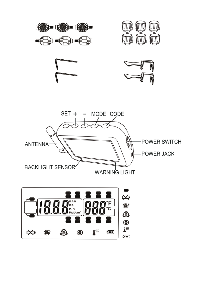
SYSTEM COMPONENTS IN KIT
TST-Doc-507 Manual-(B)
3
Truck System Technologies TST 507 Instructional Manual
Pressure Unit: BAR, PSI, Kpa or Kgf/cm2, user-selectable.
Temperature unit: C° or F°, user-selectable.
or
Cap WrenchesFT Hex Wrenches
Flow-through Sensors Cap Sensors
DISPLAY CONTROLS
Tire Indicator
Low Sensor Baery
Fast Leakage
High Pressure
Low Pressure
High Temperature
Display Baery
or
TST-Doc-507 Manual-(B)

4
Truck System TechnologiesTST 507 Instructional Manual
PROGRAMMING SENSOR CODES INTO THE DISPLAY
Note: It is recommended to label each sensor rst with the
provided numbering code sckers, similar to the following
paern, before you code the sensors. This allows you to know
which sensor is programmed to which re posion. You can also
write in your own sensor number paern.
AUTOMATIC CODE LEARNING (opon #1)
Note: Code all the sensors to the display BEFORE screwing them
onto the re valve stem unless otherwise noted.
• Turn the display on. You will be on the Main Screen.
• Press and hold the “CODE” buon unl it beeps and then
release it (approx. 6 seconds). You are now in the coding
mode.
• A re icon will ash and all 22 res will be displayed.
“FFF FFF” should also be displayed.
Or use your own paern:
TST-Doc-507 Manual-(B)

5
Truck System Technologies TST 507 Instructional Manual
Note: If the right front re is blinking and does not show all “Fs”
you can delete that factory test sensor code as follows:
Press the “SET” buon unl it beeps (approx. 3 seconds). The dis-
play should now show “FFF FFF.” This display indicates the re po-
sion is NOT coded and will not show on the Main Screen when
out of the coding mode.
• Normally, start coding on the right/passenger side of
the vehicle. This is posion #1 or, in the case of a trailer,
posion #T1.
• Be sure you have your rst sensor ready and keep the
remaining sensors at least two (2) feet away from the
display as to not interfere with the coding procedure.
• Hold your rst sensor to the boom of the display
and quickly press and release the “CODE” buon. The
display’s red LED should light and it should beep once.
A six (6) digit unique code should now appear on your
screen, replacing the “FFF FFF.”
Note: If a double beep is heard and the “FFF FFF” does not
change, try quickly pushing the “CODE” buon once again. This
may have to be done a few mes for the code to appear. If the
sensor does not code, check the baery voltage, be sure other
sensors are not close to the coding sensor, be sure the sensor
is touching the display, and be sure you are quickly pushing and
releasing the “CODE” buon. Call Tech Support at 770-889-9102
if none of the above works.
• Once coded, use the (+) or (-) buons to navigate to the
next re posion you want to code a sensor to.
• Again, put sensor #2 up to the boom of the display and
quickly press and release the “CODE” buon to capture
the sensor code. The “FFF FFF” should change to a new
unique code.
TST-Doc-507 Manual-(B)

6
Truck System TechnologiesTST 507 Instructional Manual
• Connue this process unl all your sensors are coded in
the correct re posions.
• Finally, press and release the “MODE” buon to go back
to the Main Screen. You should now see only the res
you coded. You have now completed the automac
sensor code set-up.
Note: When in the coding mode, the display will me-out within
approximately one (1) minute if no buons are pushed. At that
point, you will have to again hold the “CODE” buon down unl
it beeps and start the coding process again.
Note: Be sure the sensor being coded is at least 2 feet away from
the other sensors.
PRESSURE CODING (opon #2)
• Be sure your display is ON and it is showing the Main
Screen.
• Be sure your sensors are numbered. Screw the sensors
partly onto each valve stem in the order you numbered
them. Do NOT screw them down far enough to hear air
hissing out.
• Hold the “SET” buon down unl you hear a second
beep and then release.
• Navigate to the re icon you want to code that sensor to.
• Stand by that re and screw the sensor all the way down
to seat it.
TST-Doc-507 Manual-(B)

7
Truck System Technologies TST 507 Instructional Manual
• The sensor will immediately transmit its six digit code to
the display and it will be shown.
• Physically move to the next re posion you want to
code.
• Using the (+) or (-) buon, navigate to the re on the
display you are standing at.
• Again, nish screwing that sensor down to seat it. That
code will now appear on the display.
• Connue this procedure unl you have coded all the
sensor posions.
• Finally, press the “SET” buon unl it beeps to save all
the sensor codes in the display.
MANUAL CODING (opon #3)
Note: This method is mainly used to program sensor codes from
an old display to a new display if you do not have the sensors
available.
• Be sure your display is ON and it is showing the main
screen.
• Hold the “SET” buon down unl it beeps and release
(approx. 3 seconds).
• The rst “F” should be blinking (if no code was entered
previously). Use the (+) or (-) buons to change the rst
digit to the proper unit.
• Press and release the “MODE” buon to move to the
next digit posion. Again, use the (+) or (-) buons to
change that digit.
• Connue this process unl all six (6) of the digits are
properly set.
TST-Doc-507 Manual-(B)

8
Truck System TechnologiesTST 507 Instructional Manual
• To move to another re posion, quickly press and
release the “SET” buon.
• When done, press and hold the “SET” buon unl it
beeps to save the entries.
SENSOR INSTALLATION - Flow-through Sensor
• Be sure the an-the allen set screw at the sensor base
is not screwed in as to impede screwing the sensor onto
the valve stem.
• Screw the correctly marked sensor onto the valve stem
for that re posion. Tighten the sensor unl the air
stops leaking and the sensor booms-out on the valve
stem. Give it a slight twist to seat it. Do Not Over-ghten!
• Using the provided small allen wrench, ghten the set
screw onto the valve stem. This will prevent the sensor
from being removed. If necessary, you can put the screw
into the second screw hole to allow access by the allen
wrench if your rim is in the way. Keep the wrench in a
safe place for future use.
• You can now inate or deate the re through the 507FT
sensor without removing it.
SENSOR INSTALLATION - Cap Sensor
• Place the provided wrench around the sensor. You must
use the wrench to put the sensor on or take it o the
valve stem.
• Screw the correctly marked sensor onto the valve stem
for that re posion. Tighten the sensor unl the air
TST-Doc-507 Manual-(B)
Autres manuels pour TM-507
2
Table des matières
Autres manuels TST Accessoires automobiles


