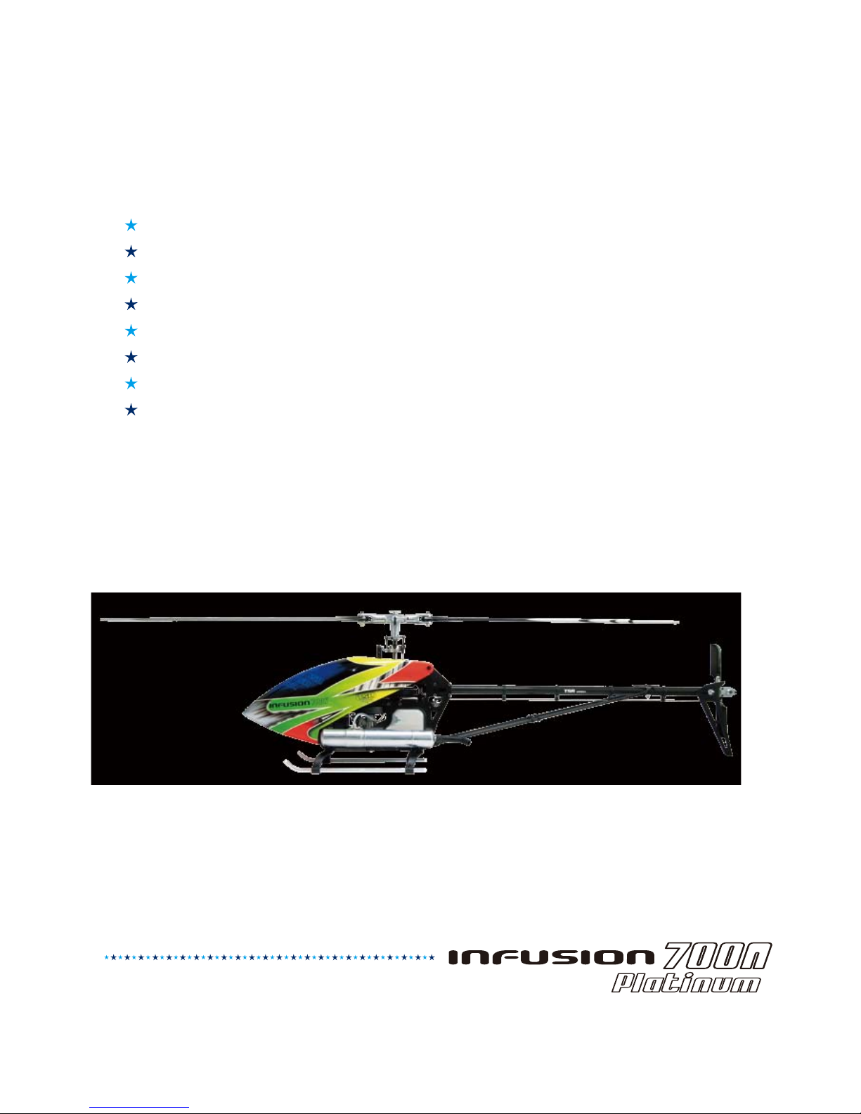
TSA model INFUSION 700N Manuel utilisateur

Welcome to the TSA family and
congratulations on your new purchase.
Please read this instruction manual carefully
to ensure you understand every step of the
build process. Most of all happy building
and we look forward to seeing you around
the world at many events.
Contents
1~2. Introduction
3. Safety instructions prior to assembly
4~5. Tools required for assembly
6~31. Parts assembly
32. Blade tracking adjustment
33~34. Operation mode
35. Flying notes
36~42. Parts package list
www.tsamodel.com
1
1: Beginners should obtain safety and technical guidance from an experienced individual, since learning alone to
operate this machine is potentially dangerous.
2: Choose a safe flying area that is free of obstruction and people.
3: Do not fly in a potentially dangerous environment.
4: Do not operate while standing on tilted ground to avoid loss of balance.
5: Do not insert hands and objects in rotating parts.
6: Keep a safe distance from the unit and be sure to operate the unit within the limits of your ability. Failure to operate
this unit properly may result in serious harm such as physical injury, damages to property, and even death.
7: Enjoy flying while observing safety rules and regulations. Fatigue brought upon by continuous operation may result
in impaired judgment that may lead to accidents.
8: Inquiries regarding repairs and services should only be made to TSA authorized dealers or TSA technical support
department. Individual lacking proper training or knowledge necessary for repair may not only impair the unit's
performance, but also increases the risk of accidents or injury. The engine must be turned off before performing any
repairs or adjustments. Repair damaged parts before storage using only TSA manufactured parts. When storing or
transporting the units, secure the unit carefully to avoid fuel loss, damage, or injury.
1: Check that tools used for assembly and maintenance has been put away.
2: Check that there are no loose screws and parts.
3: Check that the rotor blades are not damaged or cracked, especially in the vicinity of the blade holder.
4: Check the condition of the glow plugs and fuel, old glow plugs and fuel may not only cause difficulties to start the
engine, but also the possibility of stalling and crashing in mid-flight.
5: Check that electronic equipment and servos operates smoothly.
6: Check that the position of the transmitter's throttle stick and engine carburetor are at their low position.
7: Check that the receiver receives signals properly.
8: Check and ensure that all necessary parts are sufficiently lubricated.
9: Check radio is assigned to the correct mode.
1: When starting the engine, be sure to hold the rotor head firmly so the rotor head does not rotate.
2: Since the engine and muffler is heated from the operation and remains extremely hot immediately after startup or
shutdown, take extra precaution to prevent burns.
3: When taking off, the unit should be positioned at least 10 meters away from the operator. Be sure to check for people
and dangerous object in the surrounding area before takeoff.
4: Adjust the blade tracking right before takeoff.
5: Land the unit immediately if abnormal noise or vibration is observed. Then stop the engine and perform complete
check for cause of problem.
6: Be responsible when operating this unit, as reckless or improper behavior may cause accidents or injury to self or
others. Observe all safety rules and regulation while enjoy operating this unit safely and responsibly.
1: Only use glow fuel for glow model engines.
Glow fuel is highly flammable and should be handled with care.
2: Before refueling, the engine should be turned off.
3: Do not refuel near a naked flame. Do not smoke while refueling. Avoid spillage and be sure to always completely
wipe down any spilled fuel. Since fuel vapor and exhausted gas from the unit's operation are hazardous to health ,
this product is only intended to be used in an outdoor environment.
4: The fuel is hazardous. Do not consume and avoid getting fuel in the eyes. If an accident or swallowed occurs, obtain
professional medical advice/treatment immediately.
5: Fasten the cap on the fuel bottle tightly and store in a cool shaded place. Keep the fuel out of reach of children. The
ideal storage temperature should be around 10°C.
While in flight
Fuel for engine
In-flight safety inspection
Pre-flight inspection
2
1: Immediately inspect parts after every flight. Be sure to replace, retighten any missing or loose screws and replace
any damaged parts.
2. Wipe down grease, oil, dirt and dust with a clean cloth.
3. If the unit is to be stored out of operation for a long period of time, completely drain remaining fuel from
the fuel tank and carburetor.
4: Store the unit in an area free of direct sunlight, or other areas that may result in rise in temperature (e.g., car).
Instead, store in a shaded and ventilated area, and keep out of reach of children.
After-flight safety inspection
1: To reduce the risk of accidents and injuries, do not use parts other than those found in this manual or TSA catalog.
TSA will not be responsible for problems caused by using non-genuine TSA parts.
2: If the rotor blades should strike the ground during flight, there may be tiny cracks or loosening in various places
even though damages may not be clearly visible to naked eyes. If damage to the rotor blade is not fixed before
flight, cracks and loosening may increase during flight that would lead to severe consequences. The rotor head
may disassemble from the blade holder, which spins at a speed of 1200/2000 rpm, and may fly off from the blade
holder. If in doubt regarding the condition of any part, replace the part immediately using only genuine TSA parts.
3: TSA will not be held responsible for damages or crash as a result from any loose screws and/or improper
maintenance.
4: Radio wave transmitting distance is approximately one kilometer or more, therefore operator must check no other
operators in the surrounding vicinity are using the same radio frequency.
5: This remote control model is not a toy, rather a precise machine. Proper assembly and adjustments must be made
in order to avoid the risk of injuries or accidents. Operator should operate this unit safely and properly. Failure to
operate this unit properly may result in serious harm such as physical injury, damages to properties, and even death.
The operator is responsible for all damages, because TSA cannot control how the unit was assembled and used.
6: Recommended 14 years .
Warning
Caution
Please abide by regulations in your county while enjoying the
pleasure brought to you by the series.
TSA 700N
+
1. Before assembly, read the instruction manual thoroughly and familiarize yourself with the unit's structure
and assembly procedures. Failure to assemble the unit properly may not only impair performance but also
increases the risk of danger.
2. Before assembly, check description and quantity of parts. In the event of missing or defective items, contact
retailer of original purchase where authorized distributor or TSA support department can be located.
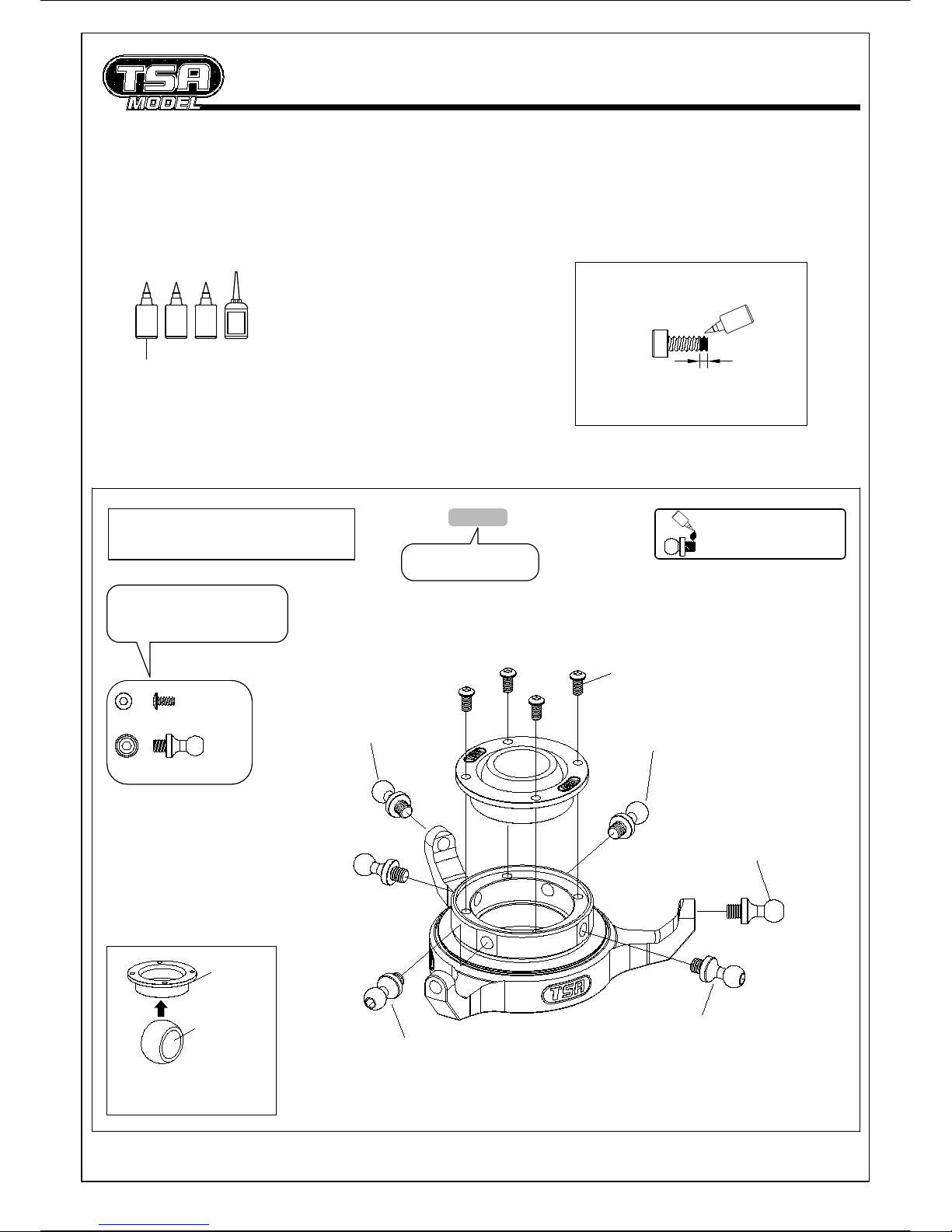
3. Apply lubricant and retainers on locations as indicated .
4. In the instruction manual, refer to the left hand column to check the type and quantity of parts.
3
Glue width :1.5mm
Lock
Preassembly precautions
Diagram for applying thread lock
Swashplate Assembly
Parts order number
Part name and quantity in
this diagram is to 1:1 ratio
T-016-05
Lock
Please apply loctite when
locking all metal screws .
Insert pivot ball in the above illustrated
orientation. The ball will clip in and
centralise easily.
Coupling
Pivot ball
(Ø12)
Assembly Tip
M2-4 Bind Screw 4
12mm Ball 6
12mm Ball
M2-4
Bind Screw
Lock
SG
CA=Cynoacrylate adhesive
CA
AB
Self-furnished
12mm Ball 12mm Ball
12mm Ball
12mm Ball
AB=5 minute expoxy / A=3 : B=1
Lock=Thread lock
SG=Silicone grease

4
1
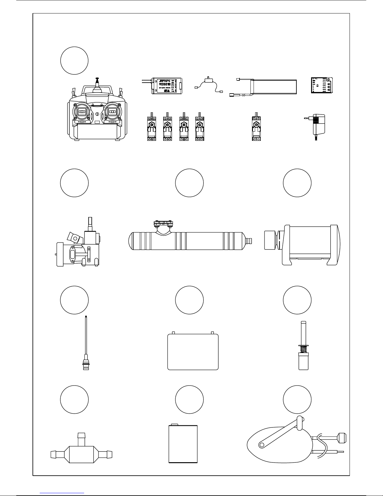
TOOLS REQUIRED FOR ASSEMBLY
Universal ball link plier
Metric ruler
(Over 30cm)
8
75.5
Cross wrench
(5.5~12)
Spanner
(6mm/8mm/12mm/21mm)
(Allen head) Screw drivers
(1.5mm/2mm/2.5mm/3mm/3.5mm/
4mm/5mm)
0
-5
-10
-15
+5
+10
+15
Pitch gauge
3 4
56
2
12
5
Fuel pump
10
Nitro fuel for model helicopter (10~30%)
EQUIPMENT REQUIRED FOR OPERATION
9
Fuel filter
8
7
Remote glow
plug adapter
12V Battery
Starter shaft
6
1.5V
5
12V
4
Starter
90 size helicopter muffler
3
2
1
90 size helicopter engine
Transmitter(7 channels) Rudder servo
Servos Charger
4.8 V
1800 mA
Receiver batteryReceiver On/off switch
Nitro fuel for
model helicopter
12V
3 Axis gyro system
PWOER
6
T-001-15 T-009-01
T-022-02
2
5M3-6 Bind screw
2
M3-6 Cap screw
M3-8 Cap screw
Custom Washer
T-005-01
T-002-05
Insert M2-4 retaining blind screws
after installing the bearing
M2-4 Bind Screw 2
M3-8
PH screw
Rigidity plate
M3-12
PH screw
Custom Washer
M3-8
Cap screw
M3-6
Bind screw
Fuel tank damper
Rigidity brace
Not included
Ø5xØ10x4
Flange Brg
T-001-15
T-005-01
T-007-05
T-003-00
M3-8
PH screw
M3-8
PH screw
Right frame
T-031-00
Main shaft bearing block
Main shaft bearing block
M2-4
Bind screw
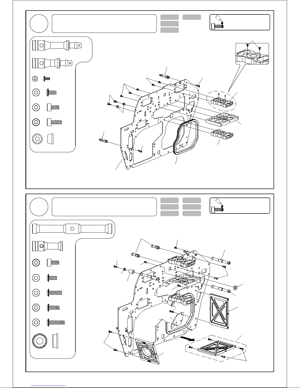
2
Main Frame Assembly-1
1Please apply loctite when
locking all metal screws .
Lock
Main Frame Assembly-2
2Please apply loctite when
locking all metal screws .
Lock
Rigidity brace
37.5mm Canopy rear support
M3-6
Cap screw
M3-6
Cap screw
30.5mm Canopy front support
M3-6
Bind screw
M3-10
Bind screw
Canopy damper
Flange washer
23mm Servo support M3-6
Bind screw
M3-6
Bind screw
61mm Cross member
M3-6
Cap screw
61mm Cross member
1
1
30.5mm Canopy front support
37.5mm Canopy rear support
1
M3-10 Bind screw
Ø5xØ10x4 Flange Brg 1
23mm Servo support 2
2
M3-6 Cap screw
2
M3-6 Bind screw
3
M3-8 PH screw
M3-12 PH screw 1
61mm Cross member 3
Centre main shaft
bearing block
M3-6
Bind screw
7
Ø5xØ10x4
Flange Brg
T-001-14
T-005-01
T-022-02
T-003-00
Left frame
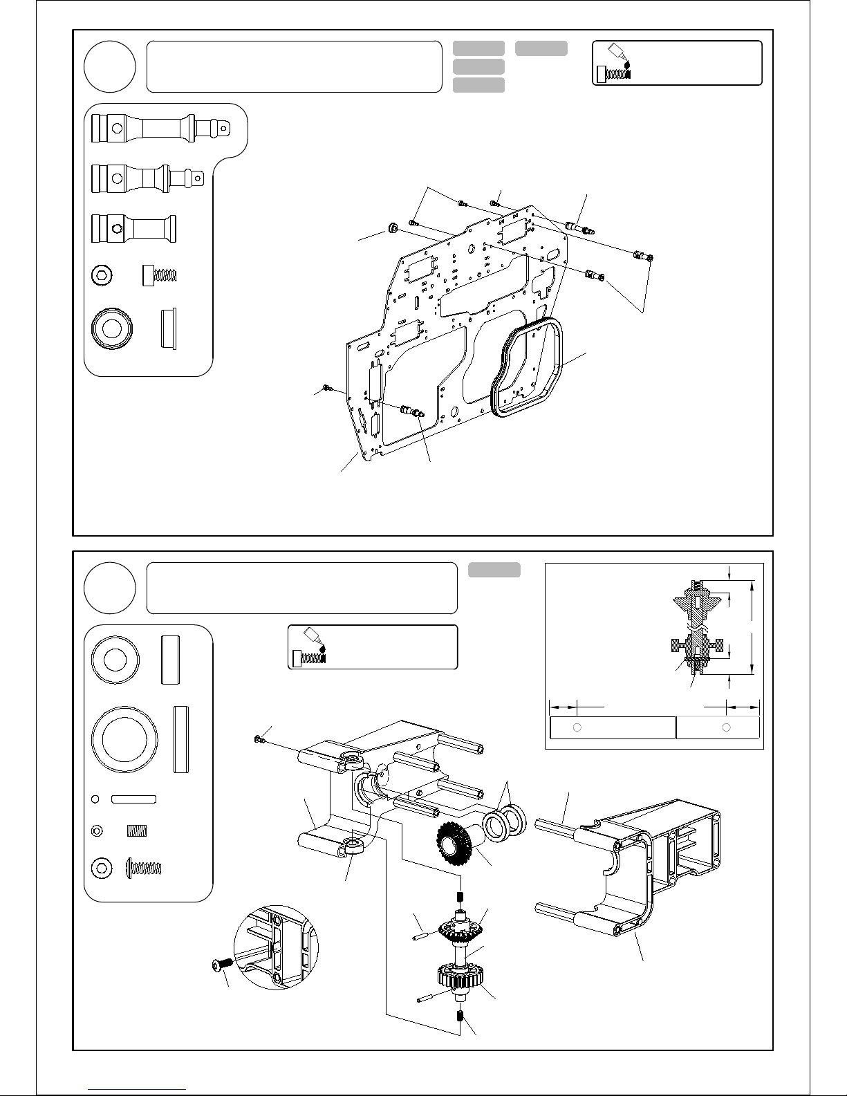
Ø6xØ13x5 Brg 2
Tail Drive Gear Assembly
57mm
Tail drive gear-25T
Bevel gear
Tail drive shaft
T-019-00
Ø2x12
Locating pin Bevel gear
M3-5 SS
2
M3-5 SS
7.5mm
Centralizing the locating pin on
each gear then tightening the
M3-5 SS grub screws. Ensure
correct gear orientation.
M3-5 SS
Locating pin
Locating pin Ø2x12 2
Plastic tail boom clamp
Hex insert
9mm
Ø12xØ18x4 Brg
Ø6xØ13x5 Brg
Plastic tail boom clamp
Ø12xØ18x4 Brg 2
M3-8
Bind screw
1
M3-8 Bind screw
Insert M3-8 into boom clamp only a few
turns as this will be tightened once boom
is installed.
M3-8
Bind screw
7.5mm 9mm
Please apply loctite when
locking all metal screws .
Lock
4
Main Frame Assembly-3
3Please apply loctite when
locking all metal screws .
Lock
Ø5xØ10x4 Flange Brg 1
2
4
M3-6 Cap screw
1
1
30.5mm Canopy front support
37.5mm Canopy rear support
23mm Servo support
M3-6
Cap screw
M3-6
Cap screw 37.5mm Canopy rear support
23mm Servo support
Fuel tank damper
30.5mm Canopy front support
M3-6
Cap screw
T-002-05
8
T-005-01
M3-8
Cap screw Custom Washer
M3-8
PH screw
M3-6
Bind screw
Rigidity plate
M3-12
PH screw
M3-8
PH screw
M3-6
Bind screw
M3-6
Bind screw
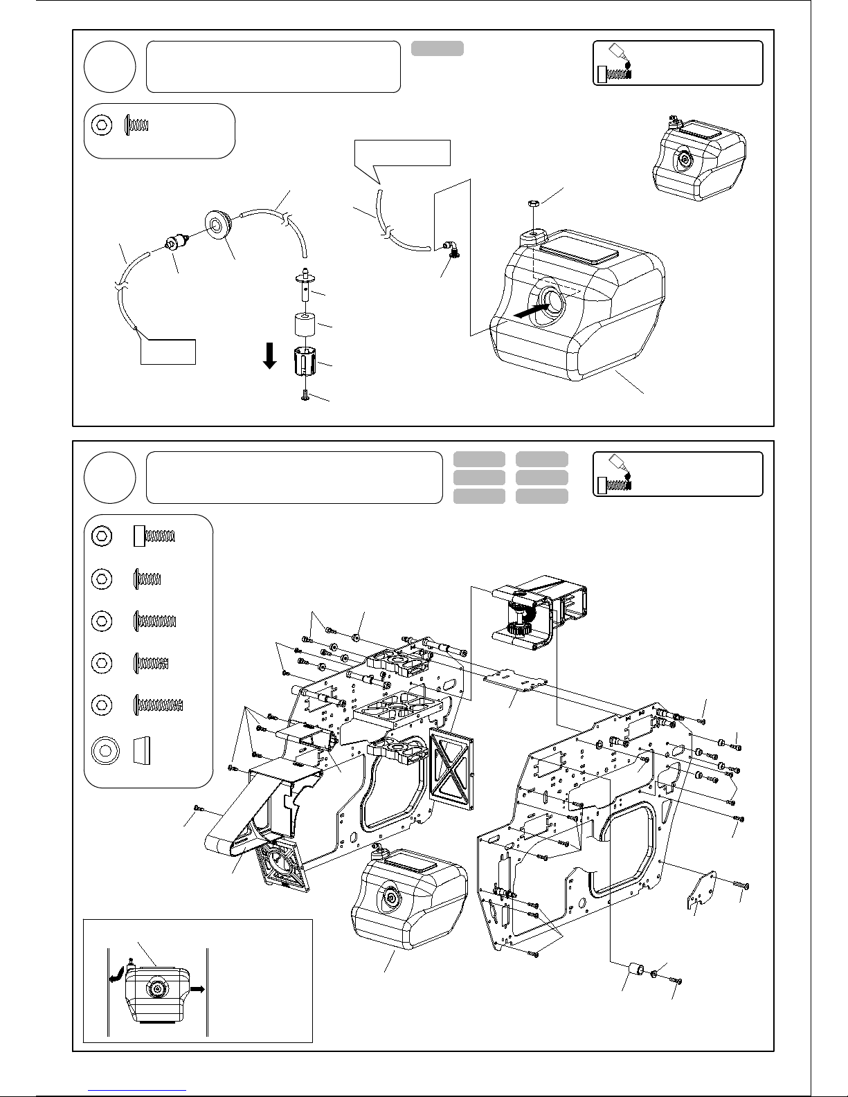
Gyro mount
M3-8
Cap screw
T-009-01
T-004-00 T-019-00
Battery mount
Fuel tank pickup
Fuel tank grommet
Fuel tank nipple
Fuel inducer
T-003-00
Inducer cover
M3-5
Stainless steel bind screw
M3-5 Stainless steel bind screw 1
Fuel tube
Ø2.5xØ5.5
To fuel nipple
Fuel tank
Hex nut
To muffler pressure nipple
90° fuel fitting
Fuel tube
Ø2.5xØ5.5
Fuel tube
Ø2.5xØ4x90L
Location point
Assembly Tip
Fuel Tank Orientation
Insert fuel tank by
pressing down on both
locating points while
sliding into position.
Fuel tank
M3-6
Bind screw
M3-8
PH screw
M3-8
PH screw
M3-8
PH screw
Gyro Plate
T-031-00
5Please apply loctite when
locking all metal screws .
Lock
Main Frame Assembly-4
6Please apply loctite when
locking all metal screws .
Lock
Fuel Tank Assembly
Flange washer
M3-10
Bind screw
Canopy damper
M3-10 Bind screw 1
6M3-6 Bind screw
M3-8 Cap screw 8
13M3-8 PH screw
1
M3-12 PH screw
Custom washer 8
Autres manuels pour INFUSION 700N
1
Table des matières
Autres manuels TSA model Jouet

TSA model
TSA model Infusion 700E Manuel utilisateur

TSA model
TSA model Infusion 600n Platinum Manuel utilisateur

TSA model
TSA model Infusion 600E Pro Manuel utilisateur

TSA model
TSA model infusion 600N PRO Manuel utilisateur

TSA model
TSA model Infusion 600E Pro Manuel utilisateur

TSA model
TSA model INFUSION 700N Manuel utilisateur

TSA model
TSA model infusion 7000n Manuel utilisateur

TSA model
TSA model Infusion 700E Manuel utilisateur

TSA model
TSA model Infusion 700E Manuel utilisateur


