Triplett GSM500 Manuel utilisateur

User Manual
GSM500
Carbon Dioxide Monitor/Controller

1
Introduction
Thank you for purchasing the Triplett
GSM500 CO2 controller. An external CO2
sensing probe is included to help you
measure the CO2 level in a closed space.
This GSM500 controller has a 120V US
AC line cord plug to get AC power from
wall power outlet, and provide controlling
function to other connected devices, such
as CO2 generator and ventilation fan.
To ensure safety, please read this manual
carefully before installation and follow up
the instructions. Store this manual in a
secure place for future reference.
Features:
Accurate & low drift NDIR CO2
measuring
External CO2 sensor to be used in a
closed space
Display real time CO2 value
Display CO2 chart with adjustable time
scale (week/day/hour/min/auto)
Auto Max. /Min. Recall on CO2 chart
Programmable CO2 zone value & CO2
center value to control output power
on/off
Audible alarm warns CO2 concentration
Target zone indicator on CO2 chart
Built-in Day/Night auto detection on
CO2 probe to override CO2 control
Backlight to assist operation in dark
place
Monitoring& Controlling CO2 value in
Green house, residential and
commercial building

2
Included
This package contains:
Meter (controller + monitor)
Operation manual
Screws and tape
Power Supply
The meter is
powered by
AC120
VAC directly.
The power plug
AC100~240VAC
is a USA piggyback plug type so you can
plug in the device you want to control.
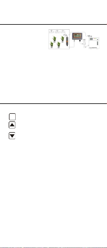
Meter Placement
An external CO2 sensing probe is
included to help you measure CO2
level in a closed space, the cable is
4.5 meter long to extend your measure
spot 4.5 meter away from display.
Please make probe and meter away
from water spray to extend the life time.
Screws are provided in package. First
using the provided wall sticker to locate
the spot where you want to hang the
sensing probe and controlling meter on
, drill to fix screw and hang devices.
3
Safety Fuse
The meter is
powered by
AC100~240
VAC directly and
provide power through piggyback socket or
EU/UK/FR/AU type socket to drive CO2
generator or
ventilation. To avoid the damage by
power overload, a 3kA@300VAC fuse
is installed in meter. Contact distributor
or shop to purchase new fuse while
necessary. See appendix for detail.
Keypad and Function LEDs
MENU
Enter setup mode.
Save and finish settings.
Select mode or increase value in
calibration and setup.
Change time scale. Select mode
or decrease value in calibration
and setup.
Power: Green on while powered
Day time: Green on while detected
light is >60 lux for 10 sec.
Output: Green on while relay is ON
ENTER

4
LCD Display

5
Operation
Plug the power plug into the wall socket
to turn the controller on. While connect
is successful, the device will show full
display with a short beep and then
performs 10 sec. countdown to warm up
and also displays firmware information
and “Warm Up” in chart display section.
Unplug the power plug to turn off the
meter. While power on the meter again,
the meter will retain the same setting
from last operation, except the chart
time will stay as 1 day while re-powered.

6
see ““ on
scale exchange
Taking Measurements
The meter starts taking measurement
after power on and updates readings
every second. If your application is for
green house CO2 control, no initial setup
is needed. In the condition of operating
environment change (ex. from high
to low temp.), it takes 30 sec to respond
for CO2 change. Do not hold the probe
close to face in case that exhalation
affects CO2.
T
he device constantly displays current
ambient CO2, set center value and set
zone value.
Trend Chart Zone
Below is a table that shows the available
time scale and the duration of each
division for corresponding scale:
Using to
available time
you choose auto
cycle, you will
LCD and time
every 20 sec.
MAX/MIN of displayed chart
At the right side of the displayed chart,
there are two numerical indicators:
Max and Min. They are the maximum
toggle the
scale. When
Time
Span
Time per
division
1min
5sec/div
1hour
5 min/div
1day
2 hour/div
1week
0.5 day/div
Auto
cycle
Cycle above

7
and minimum values on the displayed
chart. While you press down key to
change the chart time scale, these value
update as well.
Display Backlight
By pressing any key can activate the
backlight for 30 seconds to help you
operate in dark environment.
Auto Detect Day/Night
In greenhouse application, CO2 control
is not necessary while light is weak.
The built-in Photo-Cell sensor in CO2
sensing probe can automatically detect
whether it is Day (above 60 Lux) or
Night(less than 20Lux). It can override
the CO2 control and shut off the CO2
generator by turning off the output power
during the night. Conversely, if the
Photo-Cell detects light (>60Lux) and
the CO2 level is consistently low for 30
seconds, the device will start the CO2
generator by turning on output power.
Above auto detect Day/Night function
is ignored while users pick up “ Human”
mode in advanced setting. With auto
detection is ignored, the relay output
control is only decided by CO2 value,
only. Day or Night has no influence on it
Output Control
Output power is on when CO2 value is
lower Set Center-(1/2) Set zone, and off
when CO2 concentration is above
Set Center+(½) Set zone. For example,
if the Set Center is 1200ppm, and the
Set zone is 400ppm, the output power
will shut off when CO2 over 1200+
(1/2)*(400)=1400ppm, and power on
when CO2 below 1200-(½)*(400)=
1000ppm.
Above output control pattern is opposite

8
while users pick up “ Human” mode in
advanced setting. You can check from
display to know the existing setting is
Human or Plant .
In Human mode, if the Set Center is
1200ppm, and the Set zone is 400ppm,
the output power will turn on when
CO2 over 1200+(1/2)*(400)=1400ppm,
and shut off when CO2 is below
1200-(½)*(400)=1000ppm.
Target Zone indicator
From displayed chart, users can easily
know whether the current CO2 reading
is the controlling target zone or not by
checking the chart. Target zone is
indicated by triangle icons.
For example, below picture shows the
max. & min value of this time scale in
last 85 seconds is 626ppm and 542ppm
and it is all in controlling target zone.
Buzzer Alarm
Buzzer alarm default as OFF (icon )
. You may go for setup mode to turn the
buzzer alarm function on (icon ).
While the buzzer is on, it beeps when
CO2 value is over Set Center+Set zone,
and off when CO2 concentration is below
Set Center+Set zone. For example,
if the Set Center is 1200ppm, and the
Set zone is 400ppm, the beep will start
when CO2 is over 1200+400=1600ppm,
and buzzer off when CO2 is below
1600ppm.
Above high alarm buzzer working pattern
is applied to both Plant & Human mode.

9
MENU
MENU
ENTER
MENU
ENTER
ENTER
CENTER
ZONE
Setup
Hold key under normal mode to enter
setup mode.
Press key to choose the necessary
setup function and then press to
enter.
To exit setup, press key four times
till it returns to normal mode. “Center”,
“Zone”, “Re-CALI”, “ADV” and then
return to normal display is a complete
cycle of setup function.
In setup mode, if none of the keys are
pressed within 1 min, the device will
automatically return to normal status.
When entering setup mode, press
to enter “Center” value setup. The
default value is 1200ppm for general
plant. Press or to change
the value and it is 50ppm/step. Then,
press again to confirm it.
When entering setup mode, press
to enter “Zone” value setup. The
default value is 400ppm for general
purpose. Press or to change
the value and it is 10ppm/step. Then,
press again to confirm it.
ENTER
ENTER
Table des matières


