2
SAFETY WARNING
During the installation or use of control systems, users of Trio products must ensure that there is no possibility of injury to any
person or damage to machinery.
Control systems, especially during installation, can malfunction or behave unexpectedly. Bearing this in mind, users must
ensure that even in the event of a malfunction or unexpected behaviour, the safety of an operator or programmer is never
compromised.
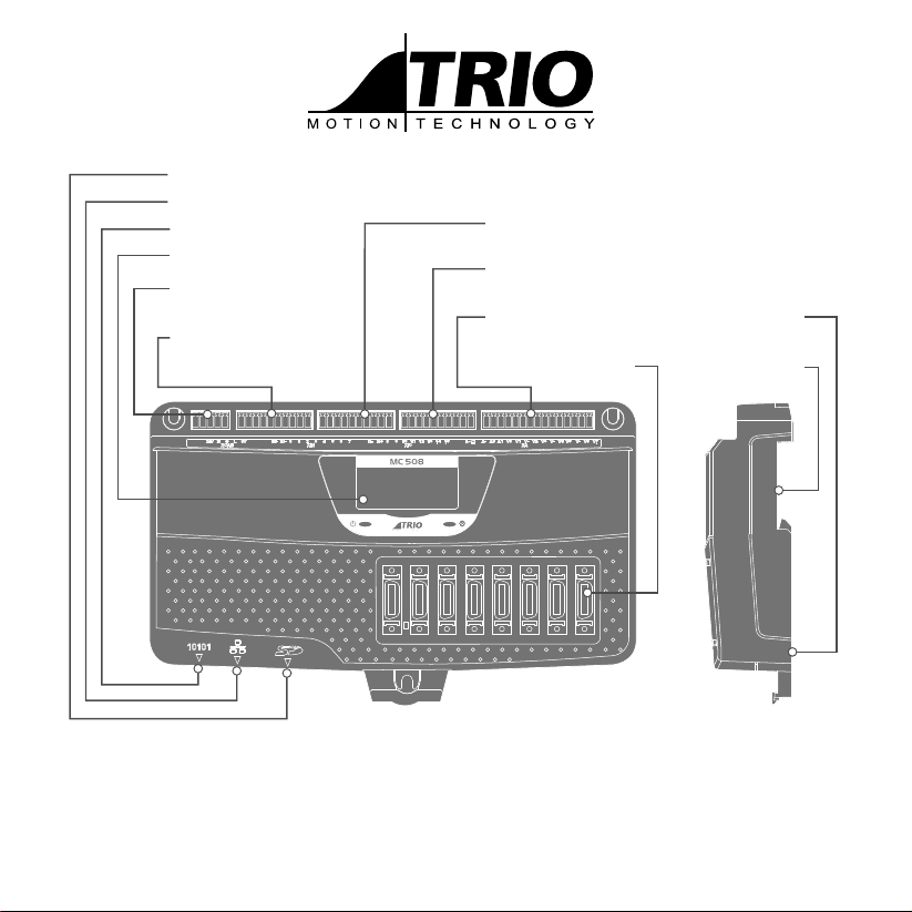
5-WAY CONNECTOR
This is a 5 way 3.5mm pitch connector. The connector is used both to provide the 24 Volt power to
the MC508 and provide connections for I/O expansion via Trio’s CAN I/O expanders. A 24V dc, Class 2
transformer or power source must be provided as this powers the unit.
This 24 Volt input is fully isolated.
THE 24V (V+) AND 0V (V-) MUST BE CONNECTED AS THEY POWER THE MC508. THE MC508 IS
GROUNDED VIA THE METAL CHASSIS. FIT A SHORT SHIELD CONNECTION BETWEEN THE CHASSIS
EARTH SCREW AND THE EARTHED METAL MOUNTING PANEL / PLATE. THE CAN CONNECTIONS
ARE OPTIONAL.
See the Technical Reference Manual for important power connection EMC information.
ETHERNET CONNECTOR (RJ45)
A standard Ethernet connector is provided for use as the primary programming interface.
The Trio programming software, Motion Perfect, must be installed on a Windows based PC that is tted with
an Ethernet connection. The IP address is displayed on the MC508 display for a few seconds after power-up or
when an Ethernet cable is plugged in.
Ethernet cable must be CAT 5 or better.
SERIAL CONNECTIONS
Pin Function Note
1 RS485 Data In A Rx+ Serial Port #2
2 RS485 Data In B Rx-
3 RS232 Transmit Serial Port #1
4 0V Serial
5RS232 Receive Serial Port #1
65V Output 150mA max*
7 RS485 Data Out Z Tx- Serial Port #2
8 RS485 Data Out Y Tx+
*400mA total shared with encoders
V+
CAN_H
SHIELD
CAN_L
V-
Input Common A
N/C
Input 0
Input 1
Input 2
Input 3
Input 4
Input 5
Input 6
Input 7
Input Common B
N/C
Input 8
Input 9
Input 10
Input 11
Input 12
Input 13
Input 14
Input 15
OP 0V B
OP 24V B
output 16
output 17
output 18
output 19
output 20
output 21
output 22
output 23
WDOG +
WDOG -
analogue 0V
Ain 0
analogue 0V
Ain 1
OP 0V A
OP 24V A
output 8
output 9
output 10
output 11
output 12
output 13
output 14
output 15
8
7
6
5
4
3
1
2