TriCom TCR-U-50 Manuel utilisateur

OPERATOR’S MANUAL
TCR-U/L-50
UHF/L-BAND RF AMPLIFIER
DOCUMENT # 90400-01465
Tricom Research, Inc.
•
www.tricomresearch.com
17791 Sky Park Circle, Suite J, Irvine, CA 92614
Phone: (949) 250-6024 Fax: (949) 250-6023

i
TCR-U/L-50 OPERATOR’S MANUAL
Revision History - Document 90400-01465
REVISION
DESCRIPTION
DATE
A
INITIAL RELEASE
12 NOV 2020
B
UPDATED P/N, SPECS, LINE DRAWING, AND
IMAGES TO REFLECT INCREASED HEIGHT
29 MAR 2021
Note: The latest version of this manual can be downloaded from our website at
www.tricomresearch.com.

ii
TCR-U/L-50 OPERATOR’S MANUAL
TABLE OF CONTENTS
1.0 INTRODUCTION
1.1 General Information ...................................................................................... 1
1.2 Abbreviations and Glossary ........................................................................... 2
1.3 Equipment Description .................................................................................. 3
1.3.1 Modes and Receive Filter Selection .............................................................. 3
1.3.2 Transmit Power Levels .................................................................................. 3
1.3.3 OLED Display ............................................................................................... 4
1.4 Amplifier Components .................................................................................. 5
1.5 Power Cable .................................................................................................. 5
1.6 Specifications ................................................................................................ 5
2.0 OPERATION
2.1 General Information ...................................................................................... 9
2.2 Controls ......................................................................................................... 9
2.3 Power On, Initialization, and Set Up ............................................................. 9
2.3.1 Pushbutton Functions .................................................................................... 11
2.4 Modes of Operation ....................................................................................... 12
2.4.1 UHF FM and AM .......................................................................................... 12
2.4.2 HQ ................................................................................................................. 12
2.4.3 SAT ............................................................................................................... 12
2.4.4 WB ................................................................................................................. 12
2.4.5 TW ................................................................................................................. 12
2.4.6 BYP L-BAND ............................................................................................... 13
2.4.7 Mode Selection Note ..................................................................................... 13
2.5 Frequency Fault and Recovery ...................................................................... 14
2.5.1 Frequency Fault, UHF SATCOM Mode ....................................................... 14
2.5.2 Frequency Fault, UHF Narrowband Modes .................................................. 14
2.5.3 Frequency Fault, WB and TW Modes ........................................................... 14
2.5.4 Recovery ........................................................................................................ 14
2.6 Bypass Operation (Power Off) ...................................................................... 14
2.7 LNA Operation Precautions .......................................................................... 14
2.8 System Warnings ........................................................................................... 15
2.8.1 High Temp Alert ........................................................................................... 15
2.8.2 High Temp Fault ........................................................................................... 15
2.8.3 High Current Alert ......................................................................................... 15
2.8.4 High Current Fault ......................................................................................... 15
2.9 Troubleshooting ............................................................................................. 15

iii
TCR-U/L-50 OPERATOR’S MANUAL
3.0 INSTALLATION
3.1 Preparation for Use ........................................................................................ 16
3.2 Mounting Provisions ..................................................................................... 16
3.3 DC Input Power ............................................................................................. 19
3.4 RF Connections ............................................................................................. 20
3.5 Auxiliary Interface ........................................................................................ 20
3.6 Firmware Updates ......................................................................................... 20
3.7 Optional Functionality and Accessories ........................................................ 20
3.7.1 Remote Face Plate ......................................................................................... 20
3.7.2 Bias-Tee ......................................................................................................... 21
3.7.3 ATAK Plug-In ............................................................................................... 21
LIST OF TABLES
Table 1-1 Nominal Performance Specifications ...................................................... 5
Table 1-2 Additional Specifications ........................................................................ 7
Table 1-3 Interconnect Characteristics .................................................................... 8
Table 2-1 Front Panel Controls ................................................................................ 9
Table 2-2 Mode Selection Default Antenna ............................................................ 13
Table 2-3 Troubleshooting Guide ............................................................................ 16
Table 3-1 DC Input Power Connector Pinout .......................................................... 19
Table 3-2 AUX Interface Pinout .............................................................................. 20
LIST OF FIGURES
Figure 1-1 TCR-U/L-50 Amplifier ........................................................................... 1
Figure 1-2 Home Display .......................................................................................... 4
Figure 1-3 Menu Function Display ........................................................................... 4
Figure 1-4 Rear Panel ................................................................................................ 7
Figure 3-1 TCR-U/L-50 Outline Drawing ................................................................ 17
Figure 3-2 DC Input Power Connector ..................................................................... 19
Figure 3-3 DC Power Cable ...................................................................................... 19
Appendix A Menu Structure… .................................................................................... 22

1
1.0 INTRODUCTION
1.1 GENERAL INFORMATION
The TCR-U/L-50 Power Amplifier (PA) evolved from the widely fielded TCR-MBA-
50v2 to meet the demands for increased communication range of existing and emerging
handheld and manpack radios utilizing UHF and L-Band waveforms. The PA is
designed for use with UHF narrowband as well as UHF and L-Band wideband
waveforms and shares the same footprint as the TCR-MBA-50v2.
• Transmit amplification for the 225-450 MHz, 1.25-1.45 GHz (L1), and 1.75-
1.85 GHz (L2) frequency ranges
• Four co-site filtered receive bands: 225-320 MHz, 225-450 MHz, 1.25-1.45
GHz, and 1.75-1.85 GHz
• Low Noise High Dynamic Range Receive Pre-Amplifier (LNA) for all bands
• Two automatic switching antenna ports: UHF and L-Band
• Active and DC Off/Failsafe L-Band Bypass
• Carrier Detect Keying and Automatic Frequency Detection
• UHF SATCOM, DAMA/IW
• UHF FM, UHF AM, HAVEQUICK II
• ANW2C and SRW Wideband Networking
• Tactical Waveforms mode for advanced waveforms
• Advanced Special Communications Mode (ASCM)
• RS-485 and USB connectivity for end-user devices and optional Remote
Face Plate and Bias-Tee
• Simple, three button menu-based user interface with Night Vision Goggle
(NVG) compatible display
• MIL-STD-810G, MIL-STD-461, MIL-STD-464 (Near Strike Lightning)
• Excessive temperature, voltage, and current protection
Figure 1-1. TCR-U/L-50 Amplifier

2
1.2 ABBREVIATIONS AND GLOSSARY
AM Amplitude Modulation
ANT Antenna
ANW2C Adaptive Networking Wideband Waveform Revision C
ATAK Android Tactical Assault Kit
DAMA Demand Assigned Multiple Access
dB Decibel
dBm Decibel referenced to 1 milliwatt (0 dBm = 1 mW)
FM Frequency Modulation
Hz Hertz
IW Integrated Waveform
JITC Joint Interoperability Test Center (DISA)
kHz Kilohertz
LED Light Emitting Diode
LNA Low Noise Amplifier
LOS Line of Sight
MHz Megahertz
mW Milliwatt
OLED Organice Light Emitting Diode
RCV Receive
SATCOM Satellite Communications
SRW Soldier Radio Waveform
TW Tactical Waveforms
UHF Ultra-High Frequency
VDC Volts, Direct Current
VSWR Voltage Standing Wave Ratio
W Watt
WB Wideband
XMT Transmit

3
1.3 EQUIPMENT DESCRIPTION
The TCR-U/L-50 (Tricom PN: 11000-00927) is a bi-directional half duplex RF Power Amplifier
(PA) designed to enhance communications in vehicular, airborne, maritime, man-portable, or
fixed-station applications. Current military and commercial waveforms are supported including
Narrowband LOS (UHF FM and AM), Frequency Hopping, DAMA/IW SATCOM, Wideband
Networking and Special Communications Modes. Four individual receive band co-site filters
with high dynamic range low noise amplifiers (LNAs) are used to cover the UHF SATCOM,
UHF, L1, and L2 ranges to greatly improve reliable communications in high co-site installations.
Harmonic filters are used to control harmonic and spurious emissions. The L-Band Bypass mode
suppresses frequencies below 30 MHz. An intuitive menu driven user interface simplifies
operation of the PA and provides status to the operator.
1.3.1 MODES AND RECEIVE FILTER SELECTION
Listed below are the receive band filter ranges with the associated PA modes. The PA
modes are listed in the format that they are displayed. Mode selection is accomplished
using the TCR-U/L-50 front panel push buttons, further described in Section 2.3:
RCV FILTER MODES
UHF SATCOM SATCOM
UHF UHF FM, UHF AM, HQ (HAVEQUICK), WB
(WIDEBAND), and TW (TACTICAL WAVEFORMS)
L1 WB and TW
L2 WB and TW
BYPASS BYP L-BAND
1.3.2 TRANSMIT POWER LEVELS
The PA has 10, 15, 20, 35, and 50 Watt RF output power levels for UHF narrowband modes and
10, 25, and 50 Watt levels for WB and TW operations. Note, L-Band is limited to 25W output
power.
4
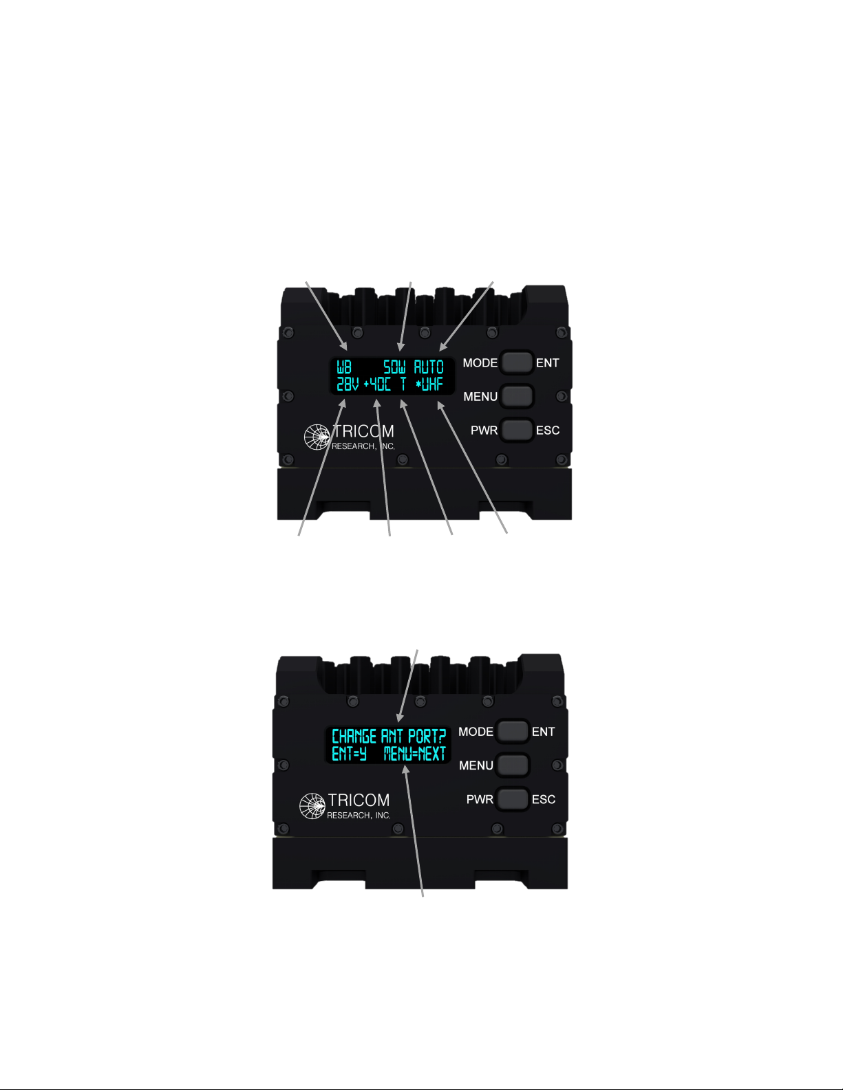
1.3.3 OLED DISPLAY
The TCR-U/L-50 NVG compatible OLED Home Display is used to indicate the mode of
operation, power level, antenna selection, DC input power, internal temperature, RCV/TX, and
in use antenna when in AUTO. During use of the Menu function, the display provides clear
user instructions. Examples of the Home Display and Menu functions are shown in Figures 1-2
and 1-3.
Figure 1-2. Home Display
Figure 1-3. Menu Function Display
MODE
POWER
ANT
VOLT
TEMP
RCV/TX
SUB MENU
ACTION
IN USE

5
1.4 AMPLIFIER COMPONENTS
The TCR-U/L-50 Power Amplifier has a sealed, rugged enclosure finished in black anodize and
designed to withstand the elements and resist corrosion. The enclosure houses all electronic
subassemblies including printed circuit board assemblies, filter and switching networks, and
interconnects.
1.5 POWER CABLE
A multi-conductor cable connects the amplifier with an external DC power source. A cable
wiring diagram cable is shown in Section 3.3 of this manual. The DC power cable used with the
widely fielded TCR-MBA-50 family of PAs may be used to power the TCR-U/L-50.
1.6 SPECIFICATIONS
Note: Information in Section 1.6 is included for reference only and does not constitute a
warranty of performance.
Table 1-1. Nominal Performance Specifications
TRANSMIT:
UHF SATCOM
Frequency Range 290-320 MHz
UHF
Frequency Range 225-450 MHz
L1
Frequency Range 1.25-1.45 GHz
L2
Frequency Range 1.75-1.85 GHz
ALL TRANSMIT MODES
RF Power Input 1-5W (10W without damage)
RF Power Output 10, 15, 20, 35, 50W Narrowband UHF
10, 25, 50W WB/TW (L-Band limited to 25W)

6
RECEIVE:
UHF SATCOM
Frequency Range 225-320 MHz with co-site filtering
Receive Gain 6 dB, 3.5 dB NF
UHF
Frequency Range 225-450 MHz with co-site filtering
Receive Gain 6 dB, 3.5 dB NF
L1
Frequency Range 1.25-1.45 GHz with co-site filtering
Receive Gain 6 dB, 4.5 dB NF
L2
Frequency Range 1.75-1.85 GHz with co-site filtering
Receive Gain 6 dB, 5.5 dB NF
BYPASS TO L-BAND ANTENNA:
Frequency Range UHF
Typical Insertion Loss 1.75 dB
Frequency Range 1-2 GHz
Typical Insertion Loss 2.5 dB
Frequency Range 2-2.6 GHz
Typical Insertion Loss 3.0 dB
Ce manuel convient aux modèles suivants
2
Table des matières
Autres manuels TriCom Amplificateur


