TRAMPA DIRT-E-TRIKE Manuel utilisateur

DIRT - E - TRIKE
USER MANUAL
Please note that this manual is a live document and currently still in progress. Please
follow all the instructions to the best of your ability as we continue to update the
manual with more relevant information and diagrams.
Version 1.1

Welcome to the Trampa
Dirt-E -Trike Manual!
The Dirt-E-Trike is a well refined and an undoubtedly fun product. Please make sure
to read and understand ALL THE INFORMATION included in this manual, before
riding. This will help you to get the most out of your trike and keep you tearing up
the trails!
We have put together a series of videos explaining many of the steps and
information outlined in this manual. Click the titles labelled “VIDEO” to be directed to
the relevant video on YouTube.
Full length Dirt-E-Trike Assembly Video
1

Contents
DIRT - E - TRIKE
USER MANUAL 0
Welcome to the Trampa
Dirt-E -Trike Manual! 1
Contents 2
Warning Message 4
Getting Started 5
Tools for Initial Assembly 5
Recommended Tools & Items for Full Maintenance: 5
Additional Tools for Assembling 18650 or 21700 Packs: 5
Removing the Original Rear Frame 6
Installing the Replacement Rear Frame 6
Installing the Spur Gear Drive to the Rear Frame 6
Installing the Wheelie Bar 7
Battery Installation 8
Example of 2x 6S 20Ah LiPo Batteries 8
Example of 84x 21700 Li-Ion Cells 8
LiPo Packs 9
18650 / 21000 Cells 10
Installing the Monster Box Battery Enclosure 11
Routing the Throttle and Brake Cables 11
Setting up the Handle Bars 13
Installing the Throttle and Brake 14
VESC Tool 15
Connect to the VESC 15
Motor Setup Wizard 16
Throttle & Brake Setup 18
Custom Profiles 19
Battery Charging & Storage 20
Battery Warning 20
LiPo Charging 21
Lithium Battery Voltages 21
Recommended Charge Current (Amps) 21
18650 / 21000 Cell Charging 23
Lithium Battery Voltages 23
Maintenance 25
General 25
Tightening of Bolts - Bolts to Check! 25
Cleaning the Trike 26
Drivetrain Health 26
Wheels 27
Changing a Tyre or Inner Tube 27
Tyre Pressure 27
Spur Gear Drive 28
2

Maintaining the Gears 28
Adjusting Backlash/ Meshing of Gears 30
Li-Ion & LiPo Battery Care & Safety information 31
Lithium-Ion Battery Hazards 31
Li-Ion & LiPo Battery Usage 31
Procurement 31
Handling and Use 31
Charging 32
Discharging 32
Storage 32
Disposal 33
Prohibited 33
What to do in an Emergency 33
Warranty Policy 34
Warranty 34
Claims 34
Warranty Periods 34
Claim Procedure 35
Contact 37
3

Warning Message
RIDING THE DIRT-E-TRIKE CAN BE VERY DANGEROUS!
E-Triking, E-Boarding or any type of sport associated with TRAMPA BOARDS LTD
products is inherently dangerous. If Trampa products are misused/used against our
guidance, the consequences could result in serious injury or death.
Full body protection is highly recommend, which includes a fully functioning
strong/certified helmet, with face guard if possible, wrist, elbow, and knee pads
SAFE RIDING TIPS
1. Never ride near roads, cars or trac of any kind.
2. Before riding, inspect the terrain for obstacles and remove any potentially
hazardous items from your route.
3. Make sure you inspect your board before riding. Ensure everything is tight and
functioning correctly before use.
4. Never ride worn out or broken/damaged equipment.
5. Make sure to use the latest VESC-Tool and firmware.
6. Use the VESC-Tool profiles to adjust the max speed and power to your skill level.
7. Don't overestimate yourself, stay on the safe side.
If you have any doubts, get in touch with us!
SUPPORT@TRAMPABOARDS.COM
4

Getting Started
Tools for Initial Assembly
Torx: T20
Hex / Allen Key: 2.5, 4, 6mm
Sockets / Spanners: 10, 13, 16mm
Heat Gun
Sidecutters
Recommended Tools & Items for Full Maintenance:
Torx: T10, T20, T25, T30
Hex / Allen Key: 2, 2.5 3, 4, 5, 6mm
Spanners / Sockets: 6, 7, 8, 10, 12, 14, 16mm
Blue Loctite 243
EP3 Lithium Grease
Additional Tools for Assembling 18650 or 21700 Packs:
Multimeter
Isopropyl Alcohol
Ruler
5
Removing the Original Rear Frame
1. Firstly undo the seat quick release clip
2. Slide the seat all the way forward so that the seat is out of the way
3. Using the 13mm socket and spanner remove the three M8 bolts holding the
rear section of the frame onto the main frame
4. Remove the rear frame from the main frame by lifting it upwards
Installing the Replacement Rear Frame
1. Place the new rear frame onto the main section of the frame ensuring that all
three mounting holes line up with the original frame
2. Using the three M8 high tensile bolts provided in the conversion kit, a 6mm
allen key, and a 13mm spanner, attach the replacement rear frame to the main
frame using the original mounting holes
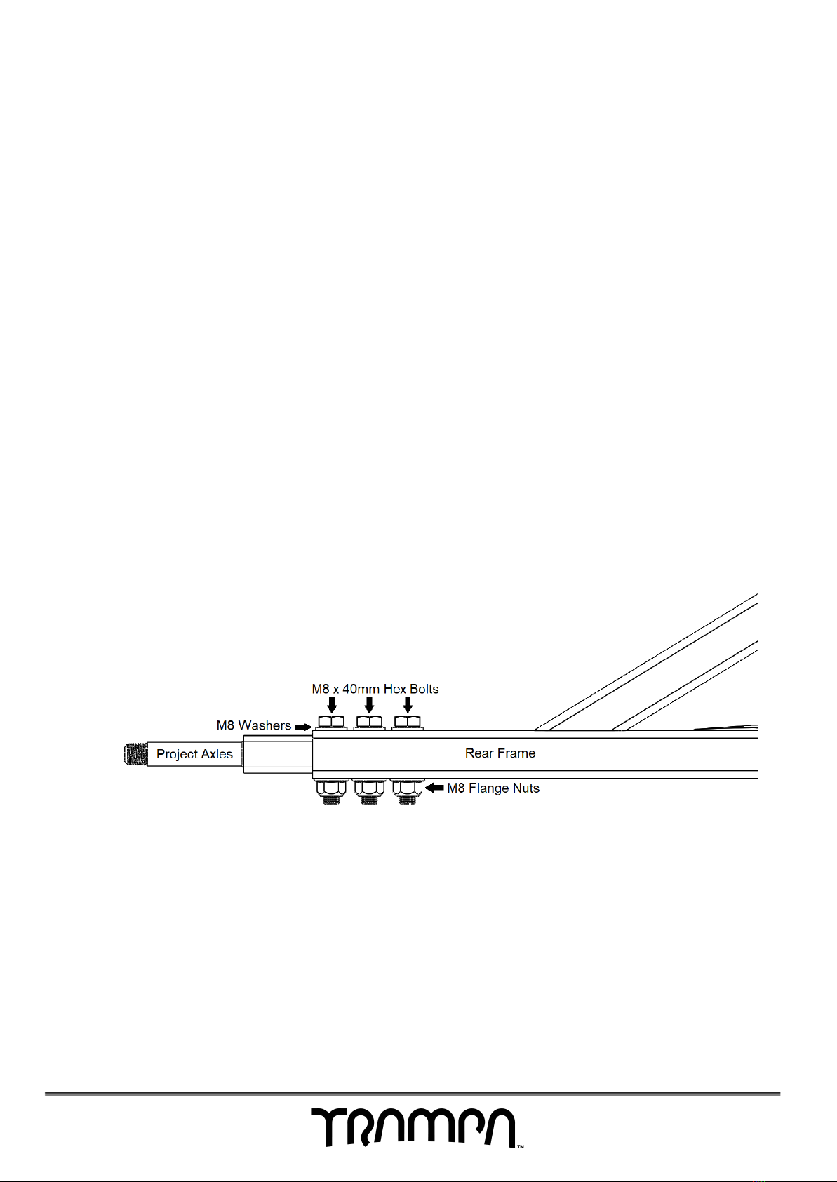
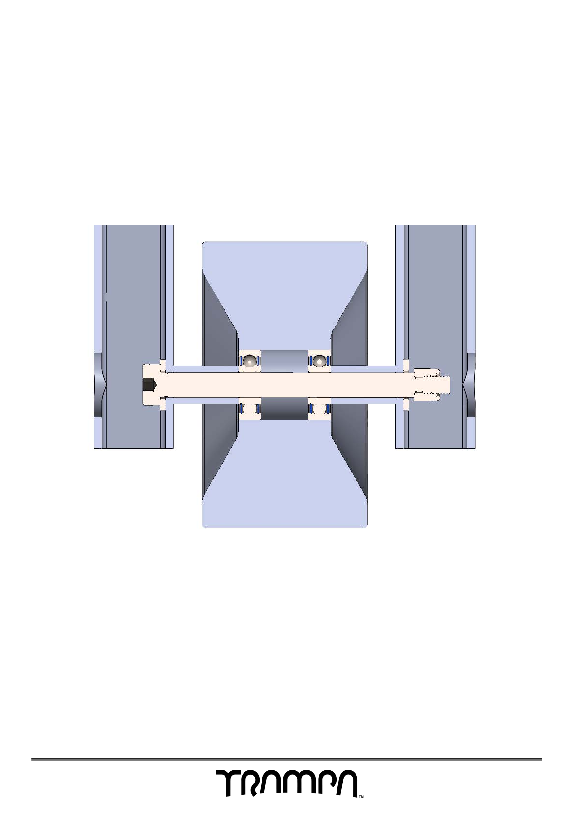
Installing the Spur Gear Drive to the Rear Frame
1. In the kit are two pre-assembled Spur Gear Drives (SGD) with axles already
installed. One is the left side and one the right side. Slide the axles into the
25mm box section with the motor facing backwards and SGD bashguard at
the bottom.
2. Place three M8 x 50mm hex bolts with M8 washers through the rear frame and
into the top of each axle and tighten with a 13mm socket or spanner.
3. On the bottom of the axe place an M8 flange nut on the remaining thread
and tighten using a 13mm socket or spanner.
6
Installing the Wheelie Bar
1. Place a M8 washer onto the kingpin and put the kingpin through the hole in
one arm of the wheelie bar followed by a 20.5mm spacer.
2. Continue pushing the kingpin through the bearings on the stickies wheel and
put another 20.5mm spacer onto the kingpin before going through the other
wheelie bar arm.
3. Place a M8 washer over the final shoulder of the kingpin and then an M6
nyloc nut.
4. Using a 10mm socket and a 4mm Allen key tighten the kingpin.
5. Spin the wheel to ensure that it spins freely - loosen the nut if it does not spin
freely.
7
Battery Installation
We currently oer three types of battery options, LiPo Packs and Li-Ion Cells (18650 &
21700). Please follow the manual accordingly.
Please take caution while proceeding with this step. Rechargeable Lithium-ion
polymer batteries are potentially hazardous and can present a serious FIRE
HAZARD, SERIOUS INJURY and/or PROPERTY DAMAGE if damaged, defective or
improperly used.
READ MORE DETAIL HERE
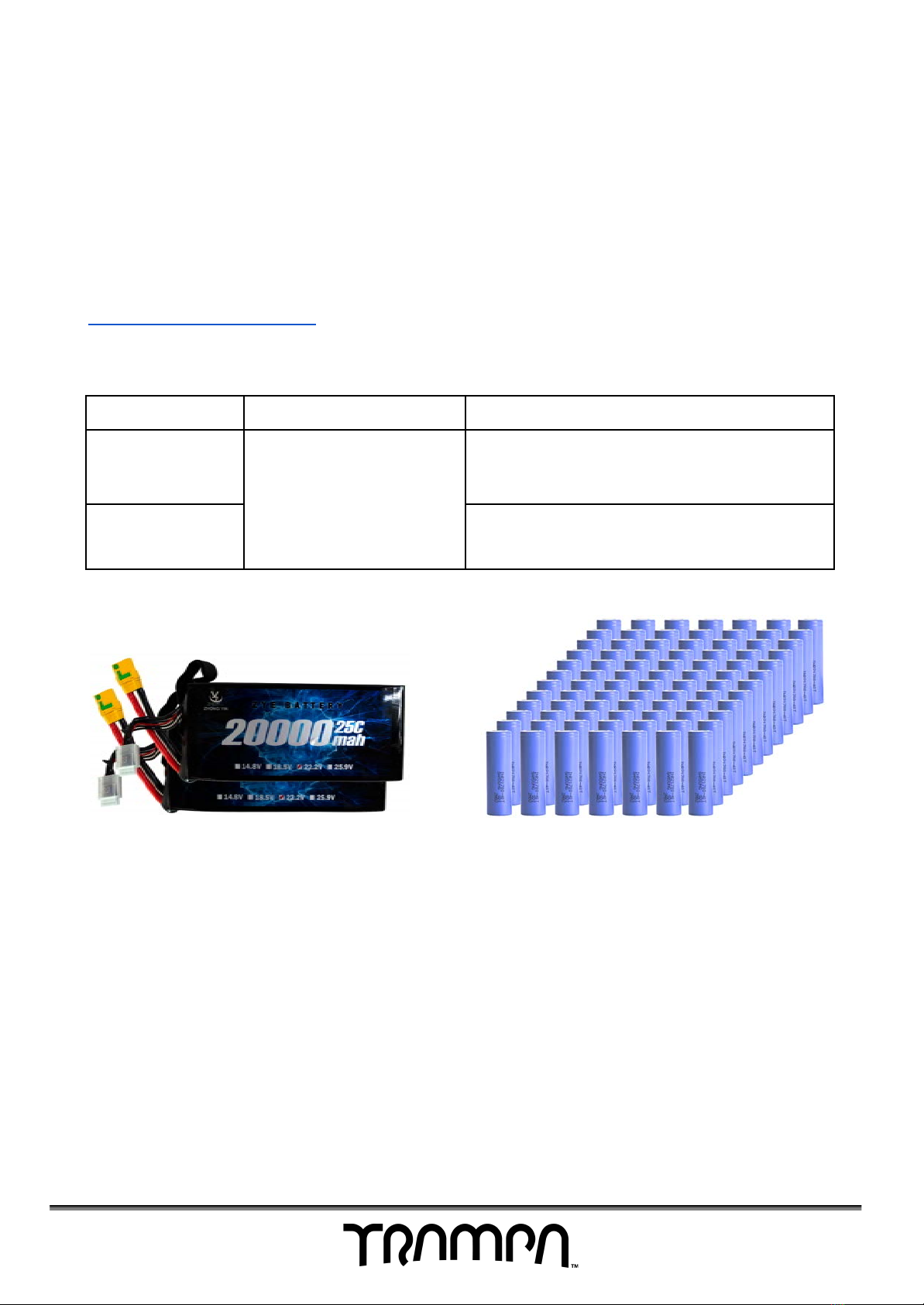
Recommended Battery
LiPo Packs
Li-Ion Cells
Classic
Monster Box
4x 6S 6.2Ah Packs*
2x 6S 20Ah Packs
2x 6S 22Ah Packs
*Extra cable required
84x 18650 Cells
Massive
Monster Box
84x 21700 Cells
Example of 2x 6S 20Ah LiPo
Batteries
Example of 84x 21700 Li-Ion Cells
8
LiPo Packs
VIDEO
1. Remove the lid of the battery box using a T20 screwdriver.
2. Place opposite sides of Velcro on both the base of the box and the LiPo cell.
3. Place the LiPo Packs down into the box making sure no wires are being
trapped or strained.
4. Check the LiPos are firmly in place. We recommend ‘packing out’ the box with
foam tape on the lid and/or edge panels to eliminate any movement of the
Lipo Packs.
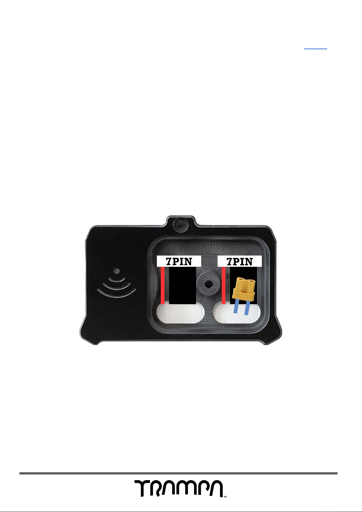
5. Connect the XT90 connectors from the batteries into the wire harness, then
plug the two remaining XT90 connectors into the VESCs as shown.
-Please double check against the diagram before plugging in.
-Incorrect wiring can result in damage to equipment or injury.
6. Feed the balance connectors and XT30 connector through the grommets into
the top of the inspection bay.
7. Carefully, place the lid of the box back on, ensuring no wires are being
trapped or strained.
8. Align the edge panels with the slots of the lid before going round and evenly
tightening the bolts.
Inspection Pit - LiPo Pack
9
Table des matières


