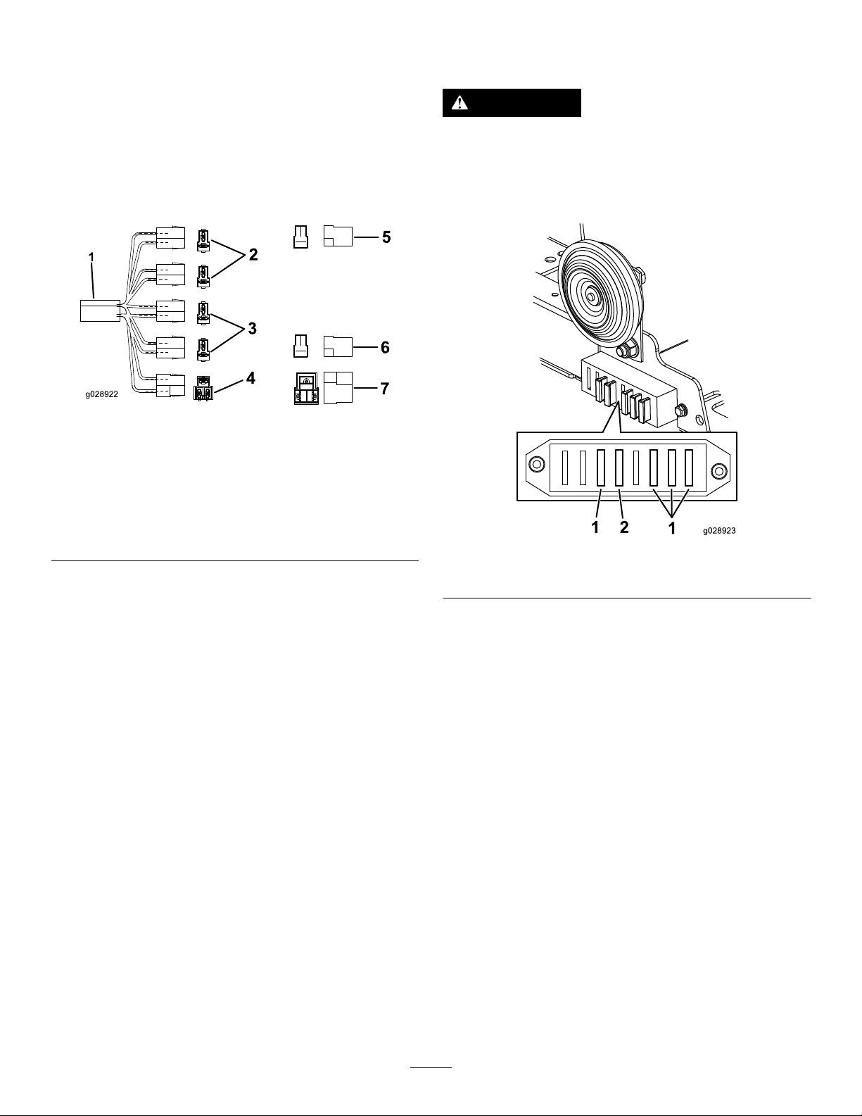
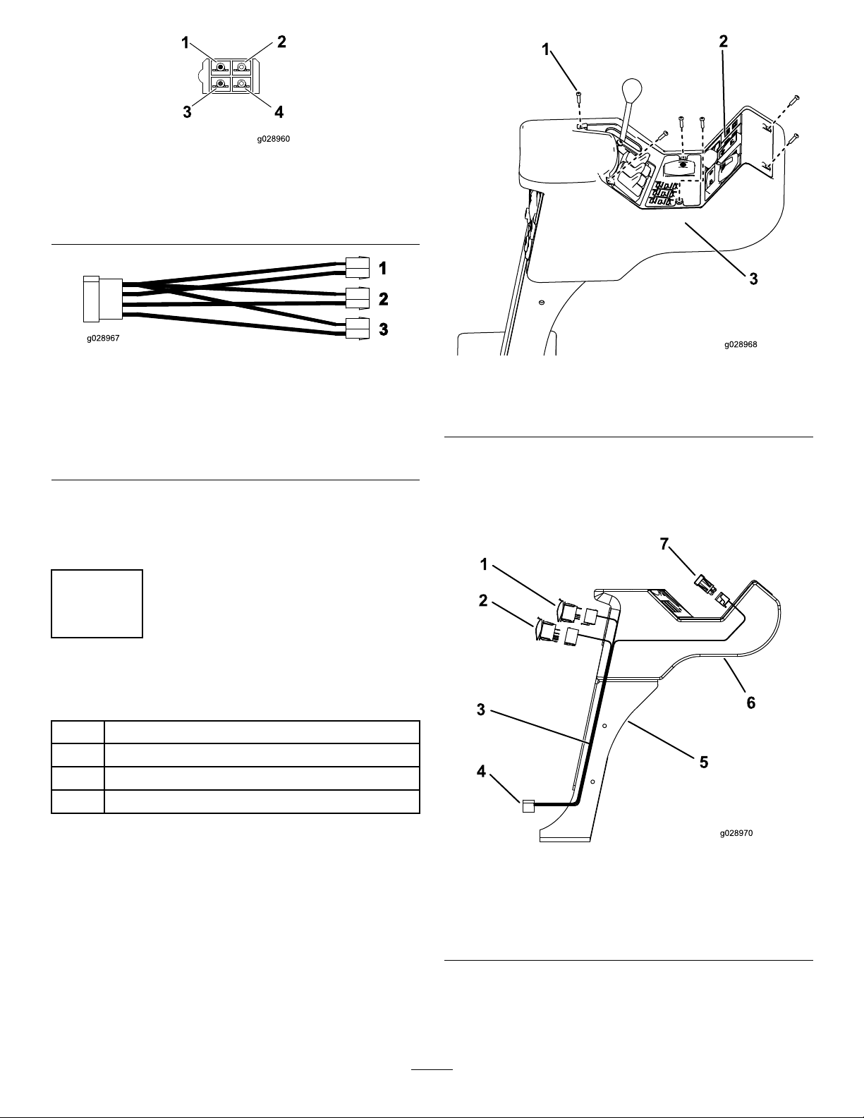
5.Ontherearfaceofthecontrolpod,abovethekey
switch,removetheswitchblankpanelsbetweenthe
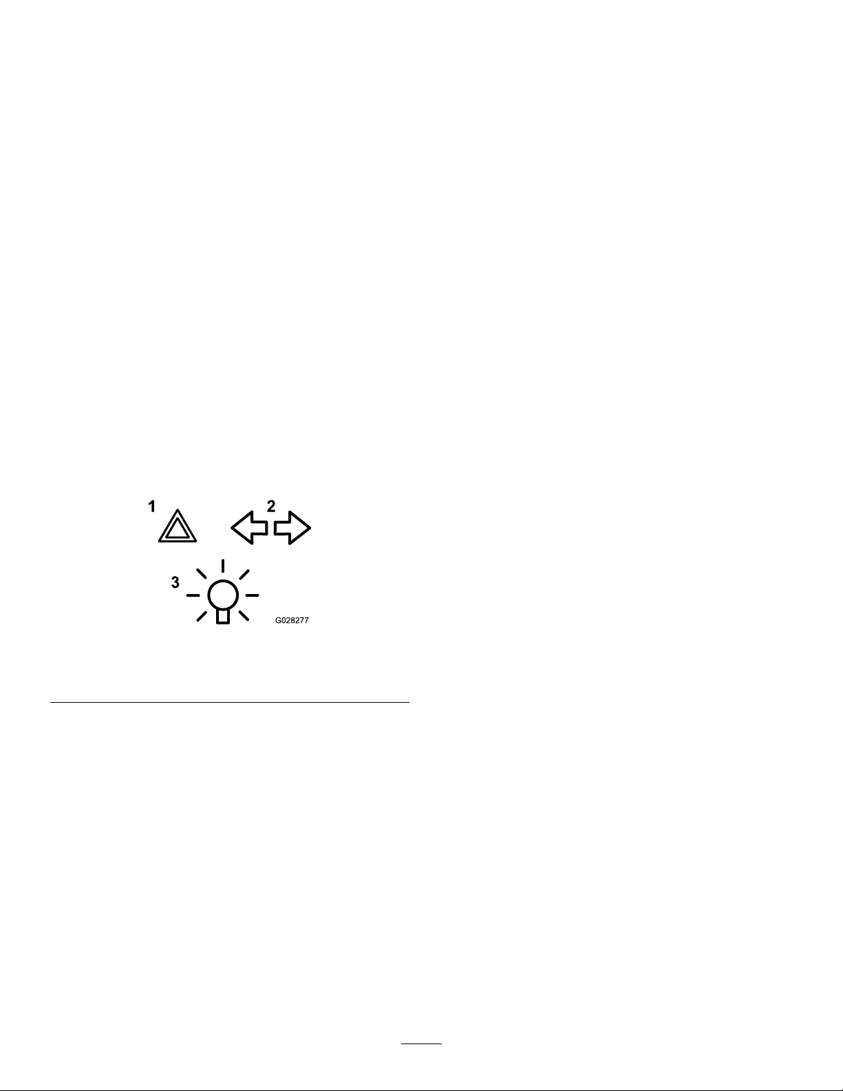
autolimitedliftandbeaconswitches(Figure20).
Figure20
1.Autolimitedliftswitch3.Hazardswitch
2.Lightsswitch4.Beaconswitch
6.Pushtheconnectorsandwiresthroughtheswitch
holes.
7.Connectthelightswitchandhazardswitchreferringto
thelabelsontheconnectorsidentifyingthem(Figure
20).
8.Inthecontrolpanel,pushouttheblankingplatenext
tothehornandinsertthedirection-indicatorswitch.
Figure21
1.Direction-indicatorswitch
9.Connecttotheconnectorlead.
5
CompletingtheInstallation
Partsneededforthisprocedure:
2Adhesivereector
20Cabletie
1Seriallabel
Procedure
1.Cabletieallcablesforthefrontlights,rearlightsand
thepressureswitchsothattheyaresecureandto
preventthemfrombecomingtrappedorchafed.
2.Connectthepositivebatterycable.
3.Testtheswitchesonthecontrolpanelandensurethat
theindicatorswitchisorientedcorrectlysothatthe
directionoftheswitchmatchesthedirectiononthe
indicators.
4.Retthecontrolpanel,ensuringthatnoconnectors
havebecomedetachedandthatnocablesarenipped
(seeFigure18).
5.Lowerandlatchtheenginecover.
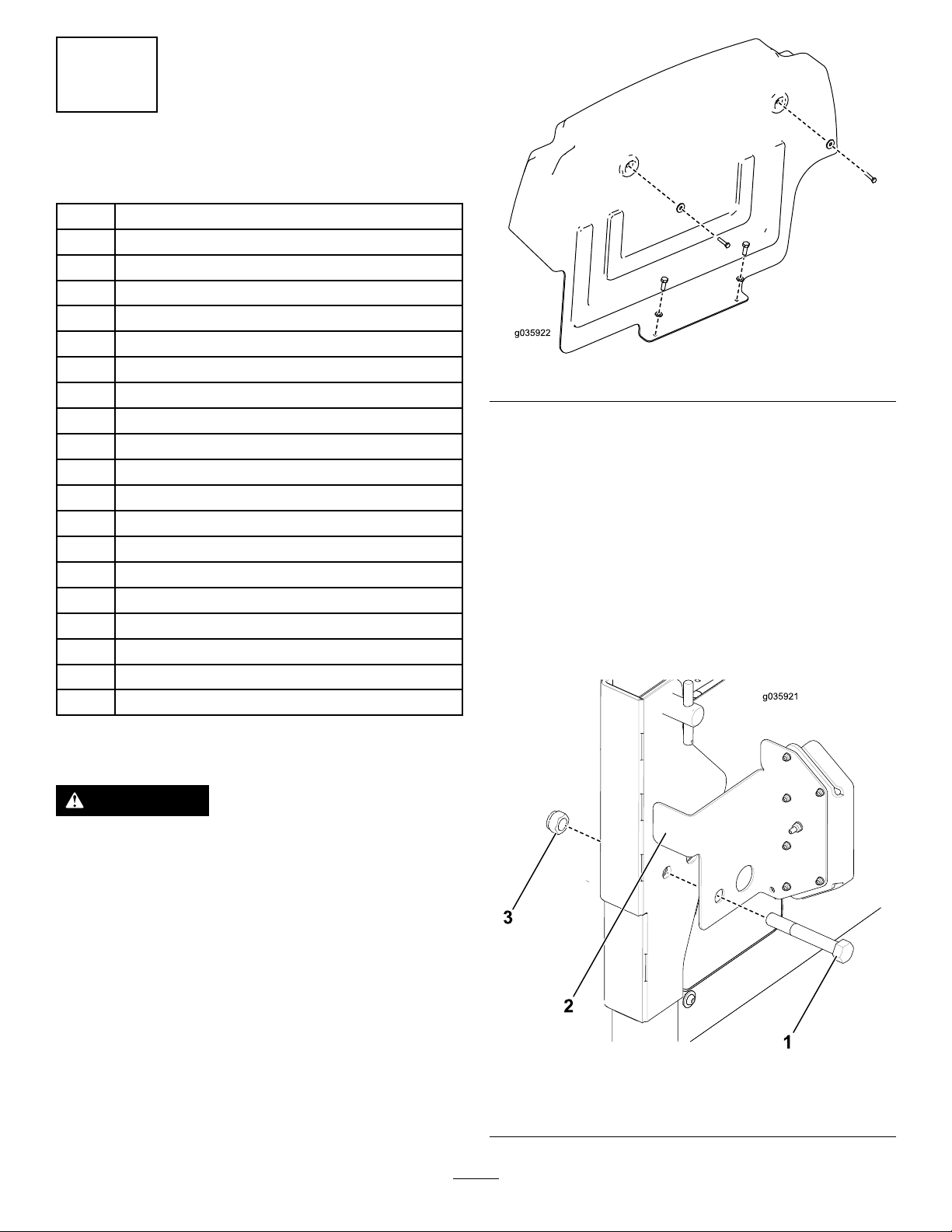
6.Applytheadhesivereectorstotheenginecover,
aligningreector’slongestedgewiththeinsideedgeof
theenginecover(Figure22).
Note:Thereectorsshouldbetted6–7cmfromthe
bottomedgeoftheenginecover.
Figure22
1.Reectors
7.Lowerandlatchtheoperatorplatform.
9