POWERED FLOW-THROUGH HUMIDIFIER
68-3074—01 4
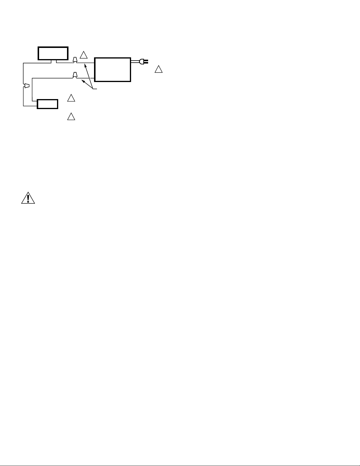
Fig. 8. Typical wiring diagram of sail switch with
humidifier.
Plumbing Saddle Valve
Hot or cold water, either hard or softened, can be used in the
humidifier.
1. Use the self-piercing saddle valve included to tap into the
water supply line at an appropriate location.
Equipment Hazard.
Improper installation can cause equipment
damage.
Do not use any line connected to an air conditioner.
IMPORTANT
• The saddle valve is not designed to regulate water
flow; the valve is either open or closed.
• Be sure to install the saddle valve handle pointing
toward the ceiling to prevent debris from clogging the
solenoid in-line filter.
NOTE: Lightly clean the copper tubing ends with fine sandpa-
per before making any connections.
2. Use 1/4 in. O.D. copper tubing and connect the saddle
valve to the inlet side of the solenoid valve.
a. Place the brass compression nut over the copper
tubing.
b. Slide the brass ferrule over the tubing.
NOTE: Do not over-tighten the compression nut. Moderate
tightness prevents leaking.
c. Insert the tubing into the solenoid valve fitting and
support the valve while tightening the compression
nut.
3. Connect a 1/2 in. hose to the humidifier drain fitting and
run it to a suitable drain.
NOTE: Slope the hose downward for correct drainage.
CHECKING INSTALLATION
1. Open the saddle valve.
NOTE: The furnace blower must be operating for the humidi-
fier to work.
2. Set the thermostat setpoint 10 °F (12 °C) above the room
temperature.
3. Set the humidity control to a high humidity setting, or
place the humidity control in the test position.
4. Observe the water running out of the drain line to be sure
the humidifier is working correctly.
5. Check for leaks.
6. Reset the thermostat and humidity control to comfortable
settings.
OPERATING HUMIDIFIER
The humidifier is controlled by the Convertible Humidity
Control. The convertible humidity control is installed either on
an interior wall in the living area, or on the return air duct.
Choose the humidity control setting using the combination
relative humidity/outdoor temperature setting scale on the
humidity control dial.
Match the dial setting to the outdoor temperature for optimizing
the humidity level to reduce the moisture condensation on your
windows. The table below can also be used to adjust the
humidity control to the recommended setting.
NOTE: As outside temperature drops, the recommended
humidity control setting is lowered to accommodate
the effects of dewpoint. These settings should reduce
the accumulation of moisture and ice on the windows
and in other areas of the house.
Some indoor activities such as cooking, showering and clothes
drying can cause excessive levels of humidity and start the
accumulation of moisture on the windows. If this condition
persists for more than a few hours, set the humidistat to the
lowest setting to turn off the humidifier. If the condition does not
improve, ventilate the house to remove the moisture.
OPERATION
The humidifier uses the principle that vapor (evaporated water)
is created when warm dry air blows over a water-soaked area.
As the vapor circulates, the relative humidity rises.
The humidity control monitors the relative humidity and
activates the humidifier accordingly. The humidifier has a water
supply that disburses water over a humidifier pad. The warm
dry air from the furnace passes over the humidifier pad,
collects moisture, and circulates it through the house.
Since humidified air feels warmer and more comfortable, the
homeowner may decide to lower the thermostat setpoint, thus
saving money on heating bills. The end result is that the
humidifier provides a more comfortable environment that is
also energy efficient.
SAIL
SWITCH
HUMIDIFIER
120 VAC
M12685
YELLOW WIRES
1
1
2
2
POWER SUPPLY. PROVIDE DISCONNECT
MEANS AND OVERLOAD PROTECTION
AS REQUIRED.
24V WIRING.
MECHANICAL
HUMIDISTAT