Titan 109 Manuel utilisateur
MODEL 109
Conveyor
INSTALLATION, MAINTENANCE AND
PARTS MANUAL
For additional copies of this manual,
please visit our website at
www.titanconveyors.com.
Go to Replacement Parts/Accessories
and select Maintenance Manuals. You can then
select the manual for your model conveyor.
SERIAL NO.
TITAN INDUSTRIES
735 INDUSTRIAL LOOP ROAD
NEW LONDON WI 54961
920-982-6600
800-558-3616 Toll Free
920-982-7750 FAX
Website: www.titanconveyors.com

8/11
2
(A) Seller warrants that the material in and the workmanship on the equipment manufactured by
TITAN will be free from defects at time of shipment. If during the rst year from the date of ship-
ment, the Buyer establishes to the seller’s satisfaction that any part or parts manufactured by
TITAN were defective at the time of shipment, TITAN will, at its own expense, repair or replace
(but not install) replacement parts. For a time purpose of this warranty, one year will constitute
2080 hours of operation based on an 8 hour day. Sellers liability under this warranty is limited
to replacement parts only and the seller will make no allowance for corrective work done unless
agreed to by the seller in writing. Charges for correction of defects by others will not be accept-
able, unless so authorized in writing, prior to the work being performed, by an ofcer of the com-
pany. Damage caused by deterioration due to extraordinary wear and tear (including, but not in
limitation, use said equipment to handle products of a size, weight and shape or at speeds or
methods which differ from information originally provided), chemical action, wear caused by the
presence of abrasive materials or by improper maintenance or lubrication or improper storage
prior to installation, shall not constitute defects. Failure to install equipment properly shall not
constitute defects. Warranty does not cover consumable items. Warranty does not cover belt
tracking or adjustment at installation or periodic adjustment that may be required during normal
operation. Refer to the maintenance manual for belt tracking instructions.
(B) Seller has made no representation, warranties, or guarantees, expressed or implied, not ex-
pressly set forth on above paragraph. Seller shall not be liable hereunder for any consequential
damages included but not in limitation, damages which may arise from loss of anticipated prots
or production or from increased cost of operation or spoilage of material.
(C) The components used in manufacture of said equipment which were manufactured by oth-
ers will carry such manufacturers’ customary warranty, which seller will obtain for buyer upon
request.
(D) No representative of TITAN has been conferred with any authority to waive, alter, vary or
add to the terms of warranty state herein, without prior authorization in writing executed by an
ofcer of the company.
(E) The foregoing is in lieu of any and all other warranties, expressed or implied, or those extend-
ing beyond the description of the product.

8/11
3
TITAN MODEL 109 MANUAL
Table of Contents
Page 2 ..................................................................................................... Warranty
Page 3 ................................Table of Contents/Return Goods Authorization Policy
Page 4 .................................................................................. Safety/Safety Decals
Page 5 .................................................................................................Introduction
I. Receiving
II. Installation
Page 6 .......................................................................................Support Assembly
Frame Assembly
Page 7 ..................................................................................Component Checklist
Page 8 ........................................................................................... Belt Installation
Page 9 ...................................................................................Belt Threading Chart
Page 10 ........................................................................................ III. Maintenance
Page 12 .......................................................................................................Motors
Page 13 .................................................................................................. Reducers
Page 15 ....................................................................................................Bearings
Page 16.......................................................................................V-Belt & Sheaves
Page 17 ....................................................................................Chain & Sprockets
Page 18 .................................................................Model 109 Blow Apart Drawing
Page 19 .......................... Model 109 Center Drive & Take-up Blow Apart Drawing
Return Goods Authorization Policy
TItan Industries has a RETURN GOODS AUTHORIZATION Procedure for all
returned items. With this procedure, we are able to streamline our process and
expedite your return.
This will require you to call a Titan salesperson prior to your sending back the item
to get a RGA number and receive instructions on how to return the item. Other
information needed at this time would be your original purchase order number, Titan
serial number, job number or invoice number. This will give our salesperson the
pertinent information needed for tracking your part or component. After receiving
you RGA number, you will have ten working days to return the item to us for process-
ing. All returned goods must have this RGA number clearly marked on the outside
of the box or crate and all paperwork pertaining to the return. Any return without a
RGA number, will be refused and returned to you at your cost. Anytime you want
to inquire about your return, please reference the Titan RGA number.
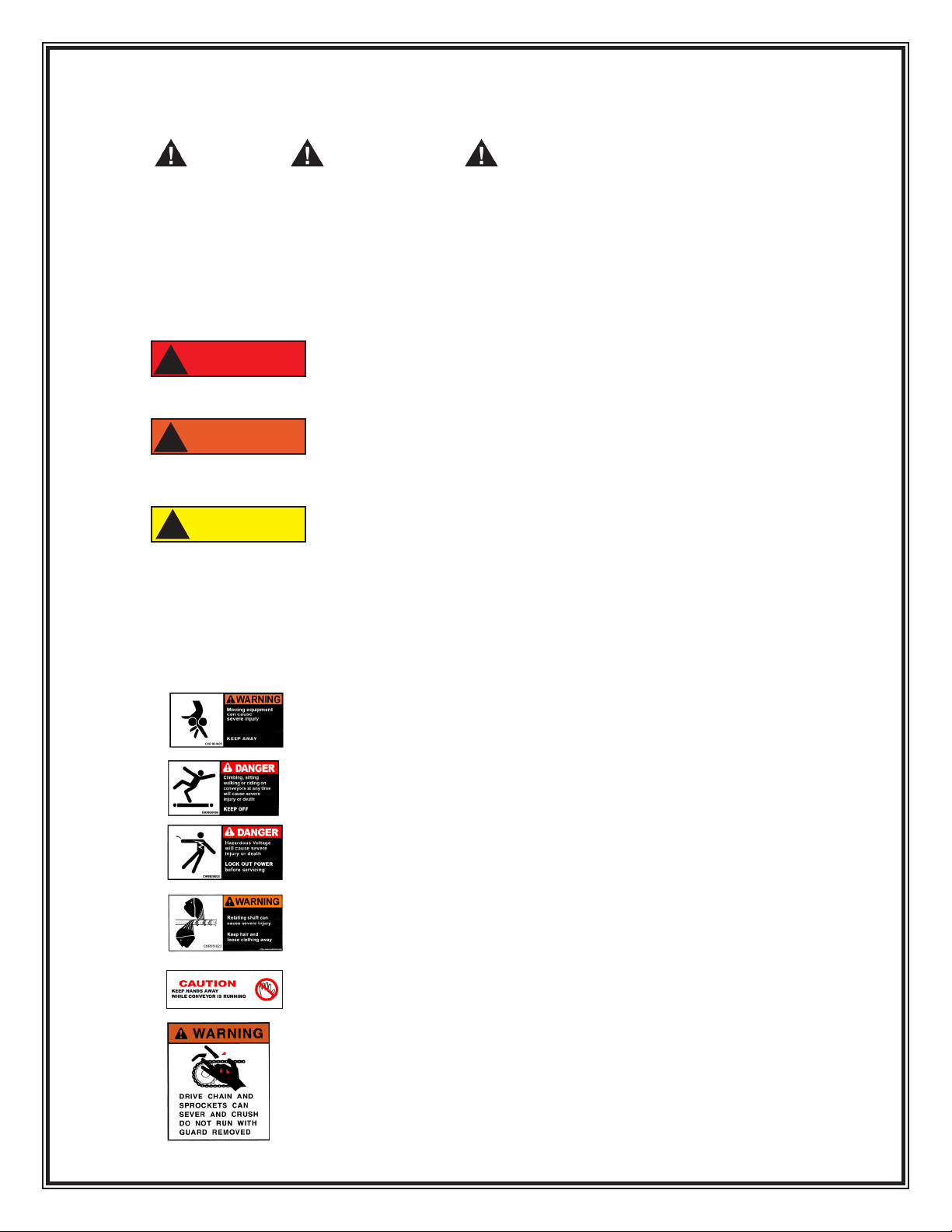
Safety
The Safety alert symbol is used with the signal words
DANGER, WARNING and CAUTION to alert you to safety
messages.
They are used in safety decals on the unit and with proper operation
and procedures in this manual. They alert you to the existence and relative
degree of hazards.
Understand the safety message. It contains important information
about personal safety on or near the conveyor.
POTENTIALLY HAZARDOUS SITUATION which if
not avoided, could result in death or serious injury.
POTENTIALLY HAZARDOUS SITUATION which if
not avoided, may result in minor or moderate injury. It
may also be used to alert against unsafe practices.
POTENTIALLY DESTRUCTIVE SITUATION which if
not avoided, may result in damage or reduce the
longevity of the equipment.
Safety Decals
ALWAYS replace missing or damaged Safety Decals.
Operational Safety
Never run conveyor without guards in place.
Keep Hands, feet, hair and loose clothing
away when conveyor is running
ALWAYS lock out power before servicing to
avoid electrical shock.
NEVER climb, sit, walk or ride on conveyor
ALWAYS keep hands away from conveyor
while moving.
CAUTION
!
DANGER
!
WARNING
!
ALWAYS keep hair and loose clothing
away.
5/12
4
8/11
5
INTRODUCTION
The management and employees of Titan Industries thank you for specifying Titan e
quipment. This manual will give you the basic information to install and maintain your
equipment. If special circumstances or questions come up call Titan at 920-982-6600.
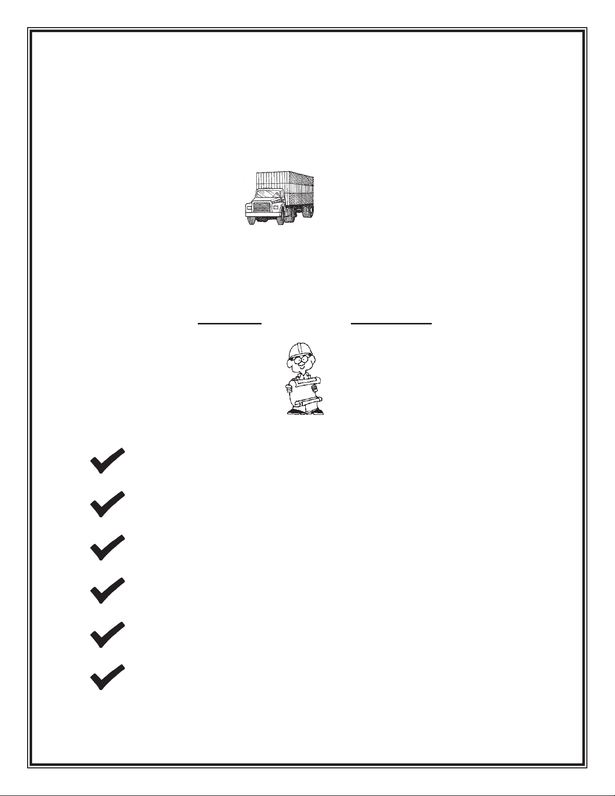
I. RECEIVING
Upon delivery of your Titan conveyor, check the packing slip or bill of lading
accompanying the unit. If any components are missing, contact Titan IMMEDIATELY
with a description of the missing components along with the conveyor serial number(s).
The serial number is found on the serial plate normally positioned by the drive.
Check the unit(s) over carefully upon arrival for damage. If you nd any damage note it
on the bill of lading. YOU MUST also le a claim IMMEDIATELY with the carrier.
II. INSTALLATION
SAFETY FIRST !!
WEAR SAFETY GLASSES, SAFETY SHOES, AND GLOVES.
HAVE AREA AROUND INSTALLATION SITE CLEARED OF DEBRIS.
LOCKOUT POWER TO CONVEYOR(S) UNTIL START-UP.
LOOK OUT FOR SHARP EDGES WHILE HANDLING CONVEYOR
COMPONENTS.
BE CAREFUL IN AND AROUND THE CONVEYOR(S) DURING
INSTALLATION. ALSO, BE AWARE OF OTHERS IN THE AREA.
ONLY ALLOW QUALIFIED PERSONNEL TO ASSEMBLE AND
INSTALL CONVEYORS.
8/11
6
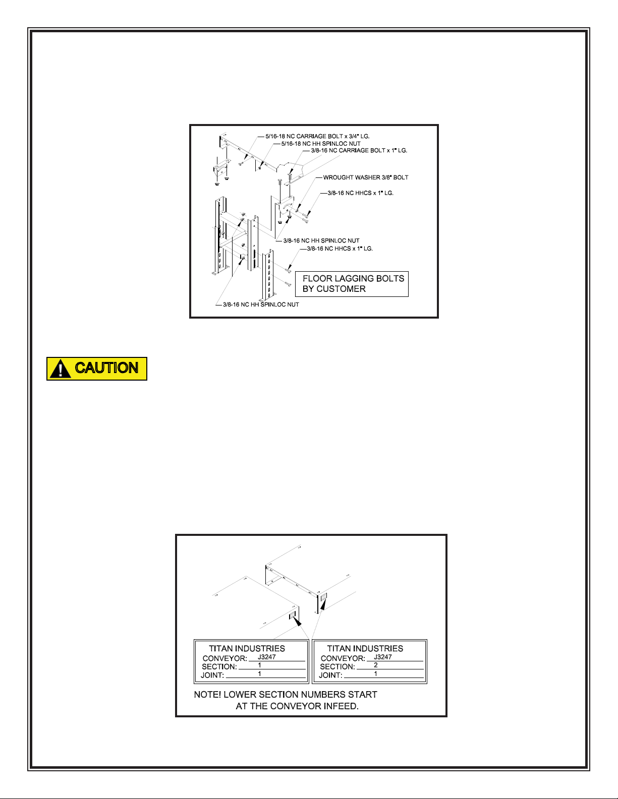
SUPPORT ASSEMBLY
Standard supports are always shipped assembled. See FIGURE 1 for a component
breakdown.
IN ORDER FOR THE CONVEYOR TO BE STABLE, THE SUPPORTS
MUST BE LAGGED TO THE FLOOR OR SUPPORT STRUCTURE. THIS
IS THE CUSTOMER RESPONSIBILITY!!
FRAME ASSEMBLY
1. To start, along side the area where the conveyor is to be installed, layout the
frame sections in their proper position according to the ordered description
or refer to your copy of the approval drawing.
NOTE: If several sections of frame are to be joined in a particular
sequence, they will be factory matched marked. See FIGURE 2.
FIGURE 1
FIGURE 2
CAUTION

8/11
7
2. Layout a line on the oor to represent the centerline of the conveyor. As
frame sections are bolted together make sure the frame remains centered
on the line.
3. Generally, if there are short sections (1’, 2’ or 4’), position them adjacent to
the drive section.
4. If a center take-up or center drive and take-up section has been provided,
position the section as close to the center of the conveyor as possible.
5. Bolt together conveyor frames nger tight. Square frames and make sure
all frames line up with adjacent section before securing all bolts. See
FIGURE 3.
COMPONENT CHECKLIST
Prior to start up use the following list to double check the conveyor components.
MOTOR Have a qualied electrician ensure the motor is wired correctly
for your power source. Check that motor is securely fastened
to the reducer or motorbase.
REDUCER Check that the proper amount of oil is in the reducer.* Make
sure a vent plug is installed on the reducer.* (A solid plug
is usually installed for shipping.) See FIGURE 10.
FIGURE 3
8/11
8
BEARINGS Double check that bearings are fastened securely. Be sure
that locking collars are tightened and set screws are secured
rmly to the shaft.
GENERAL Check that sprockets with chain and/or sheaves with V-belt
are aligned and properly tensioned.*
*Additional information available in section III Maintenance.
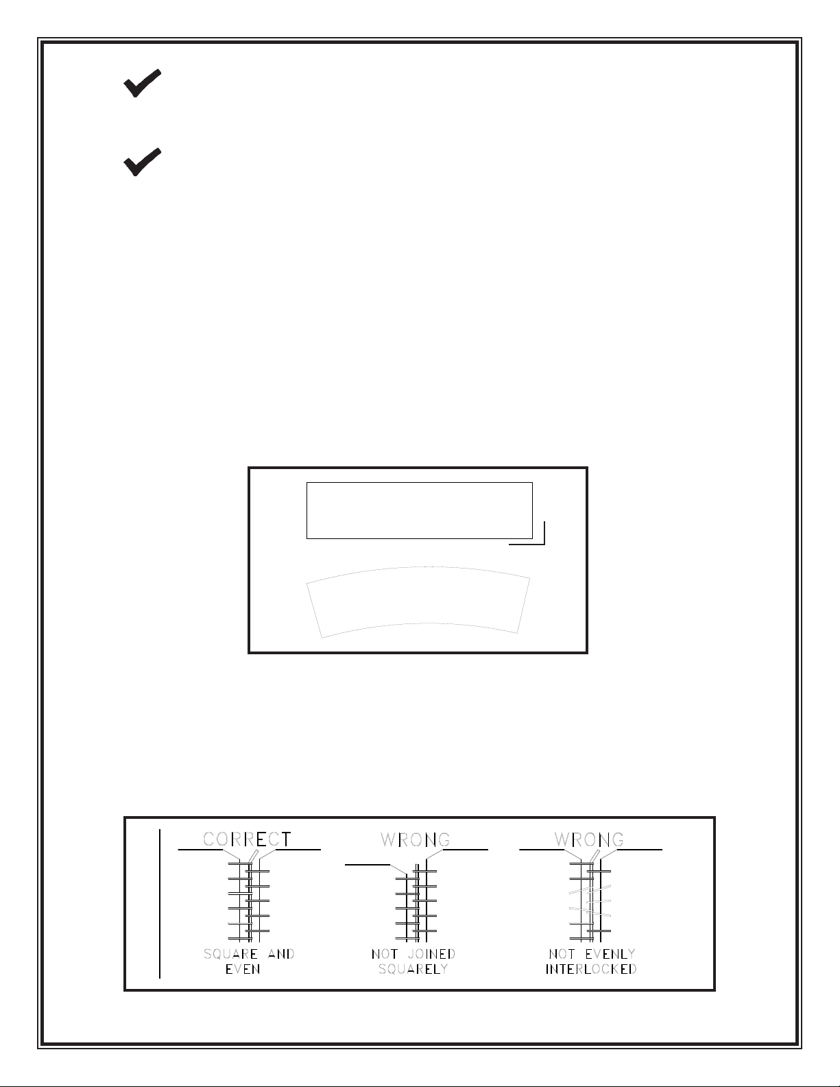
BELT INSTALLATION
1. Locate all take-up pulleys to their minimum take-up positions to allow for
easy belt installation.
2. As a double check, lay out belt on a level surface and pull tight. The belt
should lay at and be in a straight line. See FIGURE 4. At this time recheck
belt ends to ensure that they were cut squarely and that the lacing was
installed properly.
3. With typical belt threading arrangements shown on page 9 FIGURE 6 of
this manual, install the belt on the conveyor. Interlock the laced ends
squarely, and push the connector pin thru the lacing. If a metal connector
pin is used, center the pin and bend the ends over slightly to keep the pin
from working out. See FIGURE 5
FIGURE 5
FIGURE 4
YES
NO
90o
8/11
9
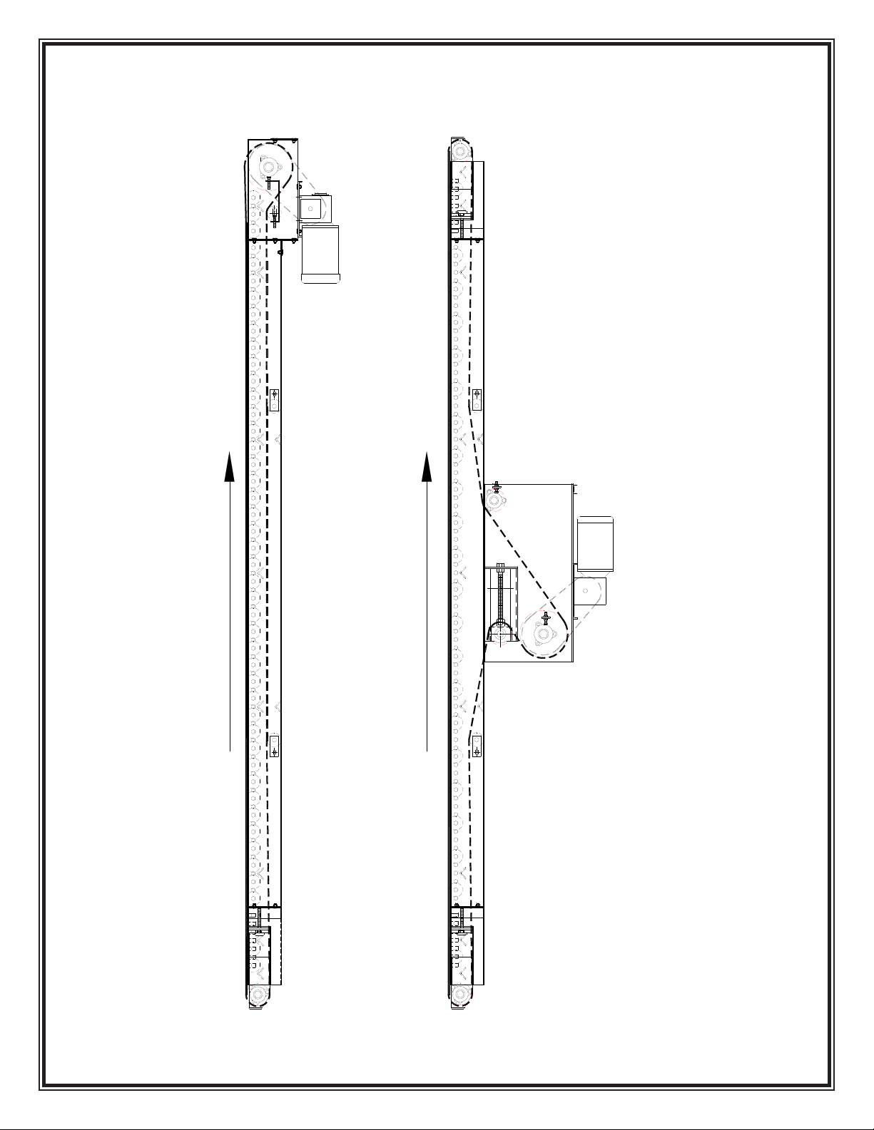
FIGURE 6
Belt Threading
BELT TRAVEL
BELT TRAVEL
MODEL 109
MODEL 109
CENTER DRIVE & TAKE UP

8/11
10
4. After making sure the conveyor is cleared off and the drive pulley is moving
the belt in the correct direction, run the conveyor. Take up slack belt with
the take-up provided until there is no slippage between the drive pulley and
the belt.
A GENERAL RULE FOR CORRECT BELT TENSION IS THAT THE
BELT MUST BE TIGHT ENOUGH TO MOVE YOUR PRODUCT AT
FULL LOAD. OVERTIGHTENING OF THE BELT WILL CAUSE
THE BELT, PULLEYS, BEARINGS, AND DRIVE COMPONENTS TO
WEAR OUT PREMATURELY.
III. MAINTENANCE
BELT TRACKING
1. The rst step in belt tracking is to make sure all pulleys are parallel with
each other and perpendicular to the frame. Once this has been done refer
to FIGURE 7 for proper tracking adjustments on end drive conveyors or
FIGURE 8 for proper tracking on center drive and take-up conveyors.
IN REF. TO LEFT HAND AND RIGHT HAND SIDES, WE AT TITAN
INDUSTRIES ALWAYS POSITION OURSELF STANDING AT THE
INFEED, LOOKING AT THE DRIVE END TO DETERMINE RIGHT
HAND VS LEFT HAND
FIGURE 7
CAUTION
CAUTION
RH
LH
Autres manuels pour 109
1
Autres manuels Titan Équipement industriel

Titan
Titan VS-32-L Manuel

Titan
Titan 535 Manuel utilisateur

Titan
Titan 610 Manuel utilisateur

Titan
Titan 305 Manuel utilisateur

Titan
Titan 114 Manuel utilisateur

Titan
Titan 759-135 Manuel utilisateur

Titan
Titan PRO-FEED 350 Manuel utilisateur

Titan
Titan 680 Manuel utilisateur

Titan
Titan 109 Manuel utilisateur

Titan
Titan 114 Manuel utilisateur

Titan
Titan 102 Manuel utilisateur

Titan
Titan 490 Manuel utilisateur

Titan
Titan 526 Manuel utilisateur

Titan
Titan 519 Manuel utilisateur

Titan
Titan 402 Manuel utilisateur

Titan
Titan 108 Manuel utilisateur

Titan
Titan 680 Manuel utilisateur

Titan
Titan 104 Manuel utilisateur

Titan
Titan 102 Manuel utilisateur

Titan
Titan 124 Manuel utilisateur


