3
SME2 - Manual - 10 - 2011
2
MAIN FEATURES
SME panel
The SME2 panel is suitable for projecting assembly.
The front includes signalling LEDs and communication port.
Phase Current Sensor
Two open core ring type current transformers are designed so as to be mounted directly on the
medium voltage insulated cables.
Residual current sensor
The IE> sensor is an open core ring type current transformer.
The sensor is installed on insulated cables so as the earth connection of the cable armour must pass
through the transformer.
Since the core embeds the three line phases, the residual current is detected.
Current sensors connections
Current sensors connections are implemented through a harness conforming with the ENEL DY1059
specification; they must be connected to the MA terminal board located inside the SME2 panel.
Voltage sensors connection
(Capacitive dividers)
Voltage sensors connection is implemented through screened cable between the fixed outlet on the
MV panel and the SME2 device through hexapolar plug conforming with the ENEL DY811 specifica-
tion.
Remote control unit
Remote control unit connections are implemented according with ENEL DY1059 specification; they
are abutted to the terminal board MB at the factory according to the connection diagram into the
device cover.
RS232 communication
The device provides a serial interface to allow a PC connection for installation, configuration, moni-
toring and diagnostic.
The firmware upgrade is provided.
To connect to the PC an adapter may be provided on request (SOC003 converter).
3
FUNCTION CHARACTERISTICS
The SME2 device performs its fault detection functions based on measure of line currents and phase
voltages; two phase currents, three phase voltages and the residual current are detected.
The following features are provided.
Earth single-phase fault
directional detection function
The function detects the occurrence of earth faults both on insulated neutral networks and on com-
pensated neutral networks, without any need of changing settings when changing type of network.
The algorithm is based on the numerical analysis of signals (FFT) through fast sampling (64 samples
per period) and phase locking algorithm (PLL); in this way the quantities are correctly measured in
Through external signal from the remote control system, it is possible to control the reversal of the
reference direction in case of line feeding from the opposed side (secondary station bar tripping
directionality); the reversal signal is provided by the remote control system through the closing of a
contact connected to terminals 8 and 9 of the MB terminal board.
The fault signal (TS67AV) is provided to the remote control unit by the closing of a contact connected
to terminal 5 of the MB terminal board.
The sensitivity of the earth directional function depends on the extension of the line and on the neu-
tral status (insulated or with Petersen coil).
The setting is based on the adjusting of a U0residual voltage[1] threshold adjustable in the 1...16% Un
range and a I0zero sequence current [2] adjustable in the 1...9 A range.
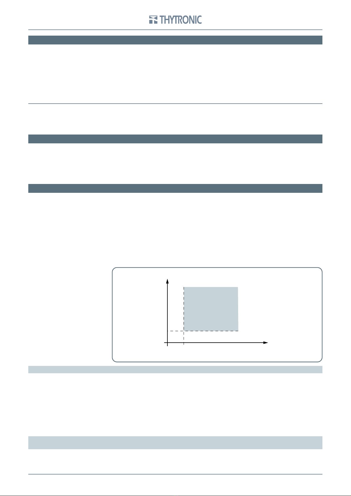
The protective element detects the directional earth fault if all the following conditions occur:
Residual voltage exceeds the U0> threshold ,
Residual current exceeds the IED> threshold IED>,
Residual current - residual voltage displacement between 60 ° and 255 ° (IED lags behind to U0with
reversed direction disabled),
All the above conditions were met for almost 80 ms.
Note 1 - The residual voltage U0is the vector sum of the three phase voltages divided by three.
Note 2 - The residual current IE is the vector sum of the three phase currents.
Double earth single-phase
or phase-phase (short circuit)
fault detection function
The L4 and L12 phase currents are measured and fault indication is provided when current in at
least one phase exceeds the set threshold a:
500 A for multi-phase faults
150 A for double earth-phase faults).
The fault signal (TS51A) is provided to the remote control unit by the closing of a contact connected
to terminal 2 of the MB terminal board.
•
•
•
•
•
•
•
•
•