THORLABS SM1L10H Manuel utilisateur

SM1L10H
Heated Lens Tube
Operating Manual

SM1L10H Heated Lens Tube
13289-D02, Rev F April 6, 2016
Table of Contents
Chapter 1 Warning Symbol Definitions ...........................................2
Chapter 2 Safety.................................................................................3
Chapter 3 Description........................................................................4
Chapter 4 Operation...........................................................................5
4.1. General Maintenance .................................................... 8
Chapter 5 Performance Specifications............................................9
5.1. Specifications................................................................. 9
5.2. Connector Pin-outs ...................................................... 10
5.3. Thermistor Data .......................................................... 11
5.4. NTC10K........................................................................ 11
Chapter 6 Warranty..........................................................................12
Chapter 7 Regulatory.......................................................................13
Chapter 8 Thorlabs Worldwide Contacts.......................................14
SM1L10H Heated Lens Tube Chapter 1: Warning Symbol Definitions
Page 2 Rev F, April 6, 2016
Chapter 1 Warning Symbol Definitions
Below is a list of warning symbols you may encounter in this manual or on your
device.
Symbol Description
Direct Current
Alternating Current
Both Direct and Alternating Current
Earth Ground Terminal
Protective Conductor Terminal
Frame or Chassis Terminal
Equipotentiality
On (Supply)
Off (Supply)
In Position of a Bi-Stable Push Control
Out Position of a Bi-Stable Push Control
Caution: Risk of Electric Shock
Caution: Hot Surface
Caution: Risk of Danger
Warning: Laser Radiation
Caution: Spinning Blades May Cause Harm

SM1L10H Heated Lens Tube
13289-D02, Rev F April 6, 2016
Chapter 2 Safety
CAUTION
Internal surface hot! Let cool before changing optics.

SM1L10H Heated Lens Tube Chapter 3: Description
Page 4 Rev F, April 6, 2016
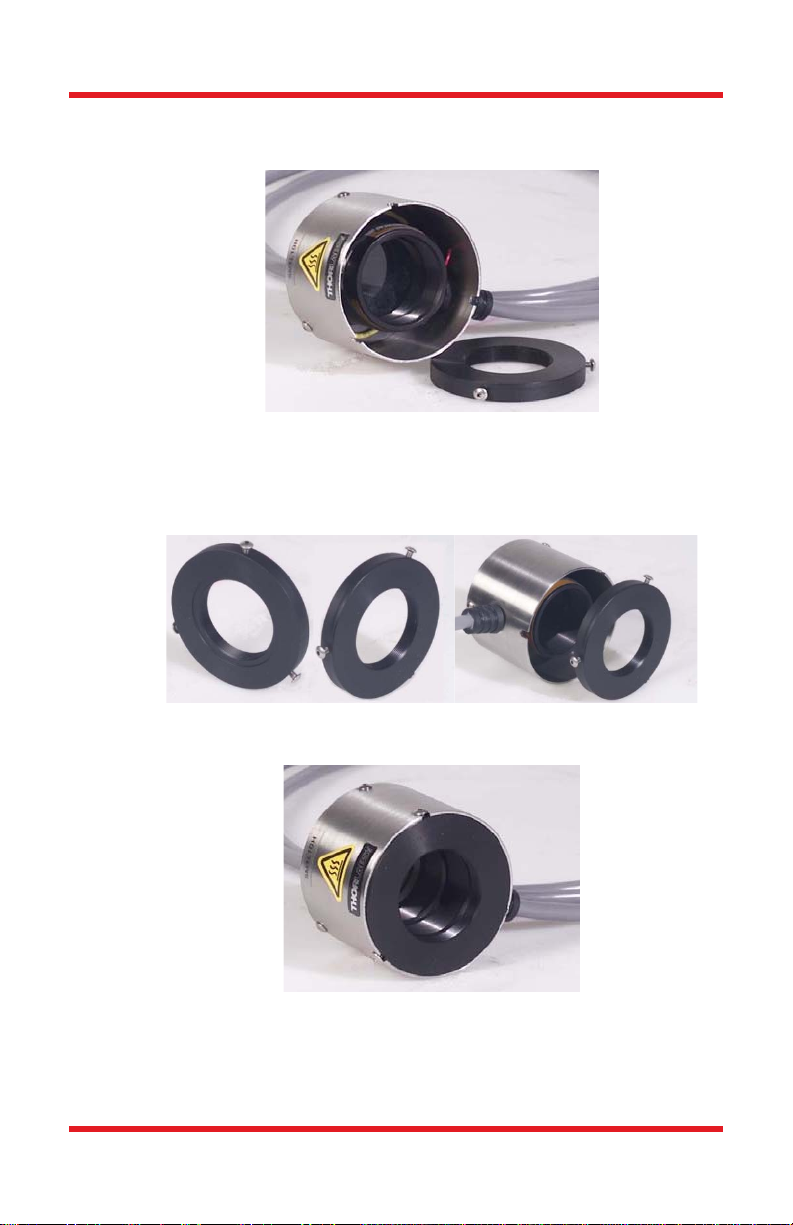
Chapter 3 Description
The SM1L10H is an actively heated lens tube that is compatible with all Thorlabs’
SM1 series lens tubes and accessories, as well as Thorlabs’ TC200 Heater
Controller.
This device allows for m ounting most of o ur 1” diameter optics and provides a
heating capability that will prevent condensation from for ming on the optic, or
allow you to take advantage of various thermal effects inherent in some optics.

SM1L10H Heated Lens Tube
13289-D02, Rev F April 6, 2016
Chapter 4 Operation
Normal Operation and Use
Caution! Internal Lens tube temperatures will be very hot! Handle with
care.
1. Install the 1” Optic into SM1L10H Heater as follows:
a) Loosen the three button head cap screws on the end cap with the
internal threads. It is not necessa ry to completely remove these
screws
b) Holding the scre ws with your fingers, slide t he end cap ou t of the
heater.
SM1L10H Heated Lens Tube Chapter 4: Operation
Page 6 Rev F, April 6, 2016
c) Place the optic into the le ns tube so it is se ated against the SM1
retaining ring that is already installed in the tube.
d) Secure the optic by threading in a second SM1RR retaining ring
(provided with the heater).
e) Replace the end cap. Orient the grooved inner surface towards the
inside of the heater and slide the screws into the slots.
f) Tighten each screw until just snug. Do not over-tighten the screws
g) NOTE: DO NOT attempt to install the opt ic without removing the
end cap first. T he SM1RR retain ing ring will NOT thread correctl y
from the end cap threads to the lens tube threads.

SM1L10H Heated Lens Tube
13289-D02, Rev F April 6, 2016
2. Locate unit on a solid, dry working surface. Unit should be secured to a
standard optical breadboard using a T horlabs’ post and base in
conjunction with a Thorlabs’ LMR1 adapter (not included).
3. Connect the heater to a n appropriate heater controller. The Hirose
connector is pin compatible with Thorlabs’ TC200 Heater Controller.
Please refer to Appen dix A for pin designations if you are using a third
party controller.
4. Operate the heater in accordance with the controller that is powering it.
IMPORTANT NOTE: The internal heating element is pr otected by a t hermal
switch that acti vates at 80 °C. At this temperature t he thermal switch will open
the connection to the heating element, causing the unit to cool down. The reset
temperature on the switch is approximately 40 °C. Once the switch cools down to
the reset point it will re-close and connect the h eating element to the power
source. The unit will then cycle on and off until the problem is corrected. Possible
reasons for th e heater to exceed 80°C include: a failed thermistor, o pen or
broken thermistor wires or connections, or improperly set control temperature.
Additional SM1 compatible lens tubes and accessories can be installed onto the
SM1L10H. Male and female threads are provided on each end of the unit. Please
take care when threading extensions onto the SM1L10H as each e nd cap is
made from Delrin and can easily cross thread or strip if over tightened.

SM1L10H Heated Lens Tube Chapter 4: Operation
Page 8 Rev F, April 6, 2016
4.1. General Maintenance
There are no user serviceable parts in the SM1L10H. If you suspect something
has failed on the unit, please contact Thorlabs for advice on returning the unit for
evaluation.
Cleaning
The unit can be cleaned using a soft, sl ightly damp cloth. Avoid using any
solvents on or near the unit.
SM1L10H Heated Lens Tube
13289-D02, Rev F April 6, 2016
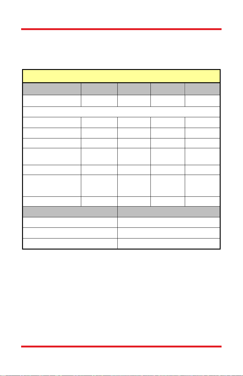
Chapter 5 Performance Specifications
5.1. Specifications
Specifications
Parameter Min Typical Max Unit
Temperature Range Ambient - 75 °C
DC Input
Input Voltage - 14 V
Input Current - - 0.7 A
Heater Resistance - 19.7 - Ohms
Thermistor
Resistance @ 25°Cb - 10K - Ohms
Thermistor Beta - 3750 -
Long Term Stabilityc - 0.200 °C
Heating Capacity - - 30 Watts
Parameter Specifications
Connector (Hirose P/N) HR10A-7P-6PC
Connector mate HR10A-7R-6S
Mechanical Dimensions Ø1.85" x 1.43" Long
SM1L10H only operates in heating mode and is protected by an 80 °C thermal switch.
a)
Thermistor is a Negative Temperature Coefficient Type (NTC)
b)
Conditions: Room Ambient u sing TC200 Controlle r. Measured directly on thermi stor – in ternal
c)
tube temperatures will differ.
Table des matières
Autres manuels THORLABS Lentille

Manuels Lentille populaires d'autres marques


Tamron
Tamron SP 70-300mm F/4-56 Di VC USD Manuel utilisateur

FujiFilm
FujiFilm FUJINON ZA17x7.6BERD-S6 Manuel utilisateur

Panasonic
Panasonic VW-W4907 Manuel utilisateur

Navitar
Navitar 1-51332 Mode d’emploi

Leica
Leica APO-SUMMICRON-SL 1:2/50 ASPH. Manuel utilisateur

Sony
Sony LKRL-Z200 Series Manuel utilisateur

 4.5/55 Manuel utilisateur")


