THORLABS SLSLLG2 Manuel utilisateur

SLSLLG2
Liquid Light Guide
Adapter with Shutter
User Guide

Liquid Light Guide Adapter with Shutter
Table of Contents
Chapter 1Warning Symbol Definitions ...........................................1
Chapter 2Safety.................................................................................2
Chapter 3Description........................................................................3
3.1.Overview.......................................................................4
Chapter 4Setup and Operation ........................................................ 6
4.1.ConnectionGuide..........................................................6
4.2.ExchangingLLGAdaptersandAdjustingAdapter
Position.........................................................................6
4.2.1.Dismantling and Installing the LLG Adapter:...............................6
4.2.2.Adjusting the Position of the LLG Adapter:..................................7
4.3.ManualShutterOperation.............................................8
4.4.ExternalModulationInput.............................................9
4.5.ProtectedMode...........................................................10
4.6.UnprotectedMode......................................................10
4.7.DefaulttoOn...............................................................11
4.8.InterlockOutput..........................................................11
4.9.Indicators....................................................................12
4.9.1.Power LED.................................................................................12
4.9.2.Status LED.................................................................................12
4.10.TimingPerformance....................................................13
4.11.TypicalPerformance....................................................14
Chapter 5Specifications .................................................................15
5.1.OpticalSpecifications...................................................15
5.2.ShutterSpecifications..................................................16
Chapter 6Interface Connector .......................................................17
Chapter 7Cleaning and Maintenance ............................................ 18
Chapter 8Troubleshooting .............................................................19
Chapter 9Mechanical Drawings..................................................... 20

Liquid Light Guide Adapter with Shutter
9.1.LLGAdapterandShutter..............................................20
9.2.ShutterController........................................................21
Chapter 10Regulatory.......................................................................22
Chapter 11Certificate of Conformance ...........................................23
Chapter 12Thorlabs Worldwide Contacts....................................... 24

Liquid Light Guide Adapter with Shutter Chapter 1: Warning Symbol Definitions
Rev A, September 8,, 2016 Page 1
Chapter 1 Warning Symbol Definitions
Below is a list of warning symbols you may encounter in this manual or on your
device.
Symbol Description
Direct Current
Alternating Current
Both Direct and Alternating Current
Earth Ground Terminal
Protective Conductor Terminal
Frame or Chassis Terminal
Equipotentiality
On (Supply)
Off (Supply)
In Position of a Bi-Stable Push Control
Out Position of a Bi-Stable Push Control
Caution: Risk of Electric Shock
Caution: Hot Surface
Caution: Risk of Danger
Warning: Laser Radiation
Caution: Spinning Blades May Cause Harm

Liquid Light Guide Adapter with Shutter Chapter 2: Safety
Page 2 CTN008800-D02
Chapter 2 Safety
All statements regarding safety of operation and technical data in this instruction
manual will only apply when the unit is operated correctly.
The unit is supplied with line cord with a North American or European plug. Make
sure your line cord fits your local outlets.
The unit is equipped with an external switching power supply for voltages from 100
to 240 VAC. There is no need to change the fuse when selecting your regional
mains voltage. There are no user serviceable parts in this product.
CAUTION
DO NOT OPEN HOUSING! The SLSLLG2 shutter and controller has no user-
serviceable parts. Do not operate without cover installed.
WARNING
Do not operate in wet or damp conditions.
WARNING
Mobile telephones, cellular phones, or other radio transmitters should not be
used within the range of three meters of this unit since the electromagnetic
field intensity may exceed the maximum allowed disturbance values
according to EN50082-1.
WARNING
Space the front side of the shutter head at least 1/8" from ferrous materials.
Keep shutter head away from strong magnetic fields. Both may interfere with
shutter operation.
WARNING
In the event of a power failure the shutter will not close. See Page 5
!
!
!
!
!
!
!
!
!
!

Liquid Light Guide Adapter with Shutter Chapter 3: Description
Rev A, September 8,, 2016 Page 3
Chapter 3 Description
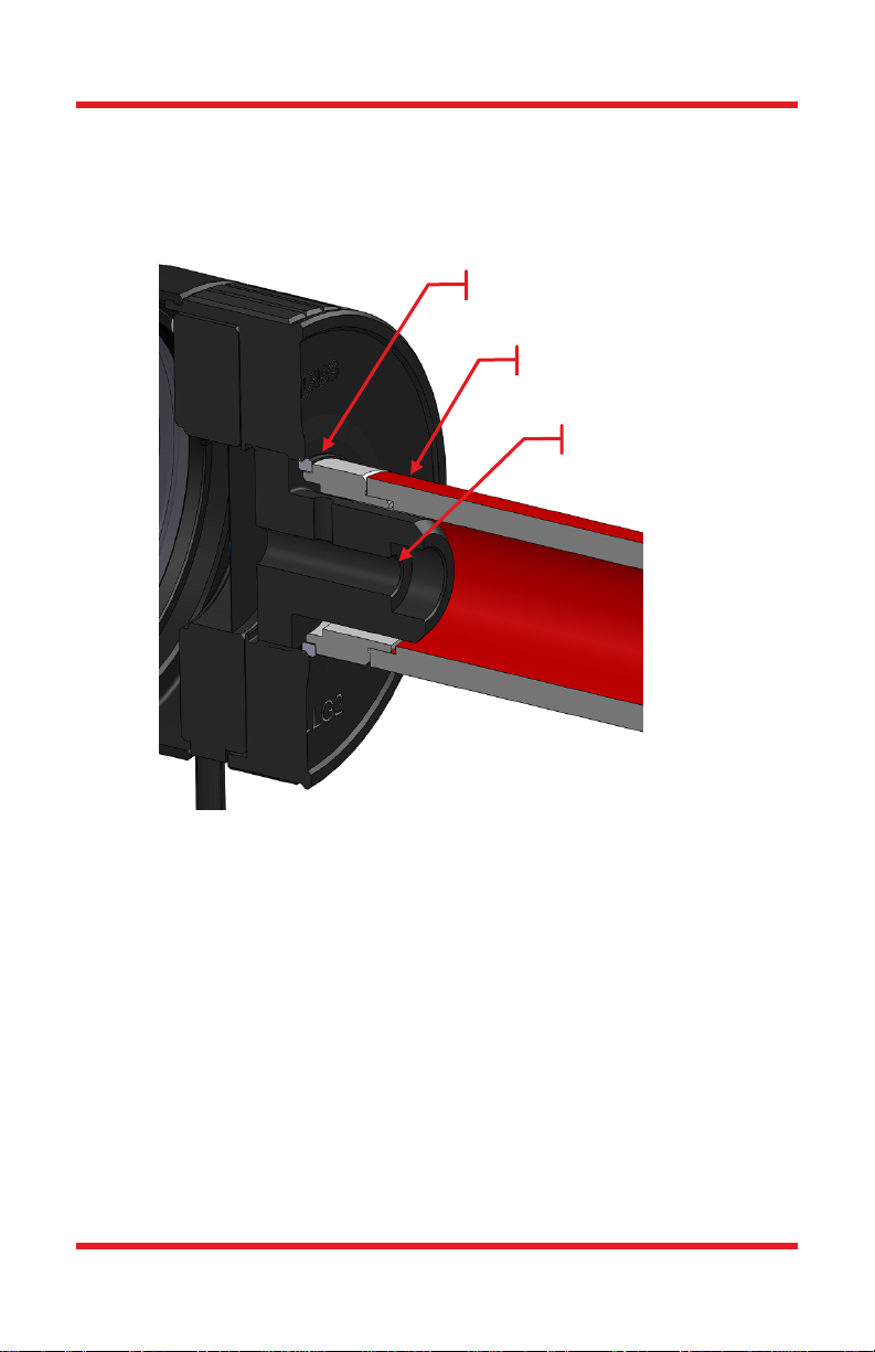
The SLSLLG2 Liquid Light Guide (LLG) Adapter with Shutter is designed to
integrate with Thorlabs’ SLS301, SLS401, and SLS402 Light Sources. The LLG
adapter couples the output of these light sources into Ø3 mm or Ø5 mm core liquid
light guides. The adapter includes an integrated shutter, , focusing lens, a Ø3 mm
LLG to SM1 Adapter, and a Ø5 mm LLG to SM1 Adapter. An external controller,
switching power supply, AC cord, and manual are included with the LLG adapter.
The shutter connects to the controller through a shielded four-conductor cable
using a four-pin, mini-DIN connector. An included controller provides the drive
levels required for optimal performance and monitors the state of the shutter. It
features a BNC connector for external modulation and an interlock output jack for
safety. A power supply (input AC 100-240V, output DC 5V) is included.
The SLSLLG2 can also be directly controlled using either the buttons on the
controller or via an external modulation source. Two buttons are on top of the
controller unit, one turns the power on and off while the button labeled ENABLE
opens or close the shutter. Manually depressing the ENABLE button will open and
close the shutter. To use the modulation input, press and hold the ENABLE button
for 3 seconds. The SLSLLG2 will power on in the last used mode, either Manual
or External Modulation Mode.
The external modulation port can drive the shutter up to a maximum frequency of
15 Hz. In normal operation, when the voltage of the external modulation pulse is
high, the shutter will open. When the voltage is low, the shutter will be closed. In
normal operation, the shutter will shut down if it is operated at the maximum
frequency for long periods of time in order to prevent overheating. In Unprotected
Mode, this safety feature is disabled and the unit may be damaged if operated for
long periods of time without thermal control.
Along with overheating protection, the SLSLLG2 is equipped with laser and blade
jam safety features. The controller detects the state of the shutter using an internal
optical sensor inside the shutter package. An optical sensor detects the position of
the shutter blade, confirming if the shutter is open or closed. This feature, when
used with the interlock connector, is ideal for applications where a laser safety
lockout is required. In the event of a failure such as a blade jam, the SLSLLG2
shutter will shut down and the state of the interlock will be indicated by a red LED
light. The SLSLLG2 shutter can detect when the blades are not operating at the
set frequency and will shut down to prevent damage to the shutter.

Liquid Light Guide Adapter with Shutter Chapter 3: Description
Page 4 CTN008800-D02
3.1. Overview
Figure 1 SLSLLG2 Side View
Figure 2 SLSLLG2 Mounted on SLS401 Light Source

Liquid Light Guide Adapter with Shutter Chapter 3: Description
Rev A, September 8,, 2016 Page 5
Figure 3 Controller Front View
Figure 4 Controller Rear View
Enable Button
Status LED
Power LED
Power Button
Interlock Jack
External
Modulation Input
Shutter Head
Jack
DC Input Jack

Liquid Light Guide Adapter with Shutter Chapter 4: Setup and Operation
Page 6 CTN008800-D02
Chapter 4 Setup and Operation
4.1. Connection Guide
1. Remove components from the case.
2. Secure the SLSLLG2 to your setup using the SM2 thread. In this
process, you can use the SM2 nut to lock the SLSLLG2 at any direction
you want, such as keeping the cable downward.
3. Connect the AC power cord to the power supply and then connect to the
AC power outlet. The SLSLLG2 is supplied with an external AC-DC
switching power supply rated at 100 – 240 VAC, 47 – 63 Hz, and 5 VDC
at 2.4 A maximum output.
4. Place the controller on a flat surface. Connect the mini-DIN connector
from the shutter head, with the arrow on the connector pointing up, into
the controller.
5. Turn the unit on by pressing the power button.
4.2. Exchanging LLG Adapters and Adjusting Adapter
Position
4.2.1. Dismantling and Installing the LLG Adapter:
Figure 5
1. Use a spanner wrench (Item # SPW602) to remove the retaining ring,
then remove the installed LLG adapter by hand.
2. Position the desired LLG adapter, then lock it in place by tightening the
retaining ring using the spanner wrench.
LLG Adapter
Retaining Ring
Spanner Wrench

Liquid Light Guide Adapter with Shutter Chapter 4: Setup and Operation
Rev A, September 8,, 2016 Page 7
4.2.2. Adjusting the Position of the LLG Adapter:
One can adjust the position of the included liquid light guide adaptor (Item #
AD3LLG or AD5LLG) to get the strongest light from the light source.
The adjustment can be done as shown in below:
1. Use a spanner wrench (Item # SPW602) to loosen the retaining ring.
2. Turn the LLG adapter by hand until the desired position is reached.
3. Secure the LLG adapter by tightening the retaining ring using the spanner
wrench.
Retaining Ring
Spanner Wrench
LLG Adapter
Table des matières
Autres manuels THORLABS Adaptateur


