3) The system default time is 1 minute. Press【START】to start working.
4) Adjust the pressure to 36 - 45 psi.
5) The remaining working time reduces gradually. When it goes to 0, the system automatically
stops.
6) After the test, raise the drain handle and put the test agent back into the fuel tank.
! Note:
· Reverse flushing is applicable to top-injection nozzles only.
· In reverse flushing, the pulse width parameter of the fuel injector has been automatically
set in the program, and users do not need to set it separately.
· Test liquid must be clean in the tank, to avoid clogging injector nozzle.
4.4 No disassembly cleaning
After the engine fuel supply system has been used for a period of time, the dust in the air and
the impurities in the gasoline will make the fuel path unsmooth or blocked. In addition, the
carbon deposits and gums produced during the combustion process will adhere to injector
nozzle, fuel inlet, exhaust valve, throttle valve and combustion chamber. Therefore, it is
necessary to clean the engine fuel supply system, combustion chamber and fuel injection
nozzles in time.
4.4.1 Preparations
1 ) Open the oil drain screw at the bottom of the main engine to release all the test liquid in the
oil tank.
2) Open the hood of the car to find the fuel inlet and return pipes of the fuel supply system of
the car.
4.4.2 Methods and Steps
【12】No disassembly cleaning (need to purchase additional accessories)
* This function requires Special cleaning fluid and tools, please use it with caution.
1) Connect the male end of the red non-dismantling pipe to the oil return pipe of the fuel
supply system (choose a suitable connector from the accessory box), and the other end to
the male end on the upper right side of the equipment.
2) Start the engine to extract 600ml-800ml gasoline from the car tank through the oil return
pipe (watching through the right window of the machine), and then turn off the engine.
3) Connect the male end of the blue non-dismantling pipe to the oil inlet pipe of the fuel supply
system, (choose the right connector from the accessory box), and the other end to the black
high-pressure oil pipe of the equipment.
4) Unplug the car oil pump fuse or oil pump relay in the condition of not affecting the work of
other systems, or find a suitable connector from the accessory box to connect the oil inlet
【09】Medium Speed Spray Value Test
1)Press the【+】and【-】key of 【FUNCTIONS/PULSE WIDTH】to select the 09 Medium
Speed Spray Value Test mode.
2)The following operation procedures is same with the 08 item.
【10】High Speed Spray Value Test
1)Press the【+】and【-】key of 【FUNCTIONS/PULSE WIDTH】to select the 10 High
Speed Spray Value Test mode.
2)The following operation procedures is same with the 08 item.
! Note:
· Flow equilibrium: Test the flow equilibrium under different rmp, when the test liquid level
at 2/3 of the counting instrument, it will pause or stop work. The deviation of the inject
value should not exceed 2% for all the nozzle of one vehicle. Please refer to the relative
tech-manual of injector nozzle, in order to observe the flow equilibrium.
· Injector shape observation: Observe the injection shape, angle uniformity of all the
injector nozzle of one vehicle. And adjust the injector nozzle open pulse width
simultaneously, observe the uniformity of the minimum open pulse width.
· Leakage test: Detect the nozzle valve seal under system high pressure.(Observe the
nozzle seal, it should not has the leakage in one minute normally.
4.3 Reverse Flushing
Reverse Flushing, The test liquid from the outlet to the inlet, it can wash the dirt out from the
internal parts of the nozzle and filter mesh.
4.3.1 Preparations
1) Add test liquid, reference to 4.2.1.
(Approximately fill about 1800 ml. The liquid level should not be lower than 1000 ml normally)
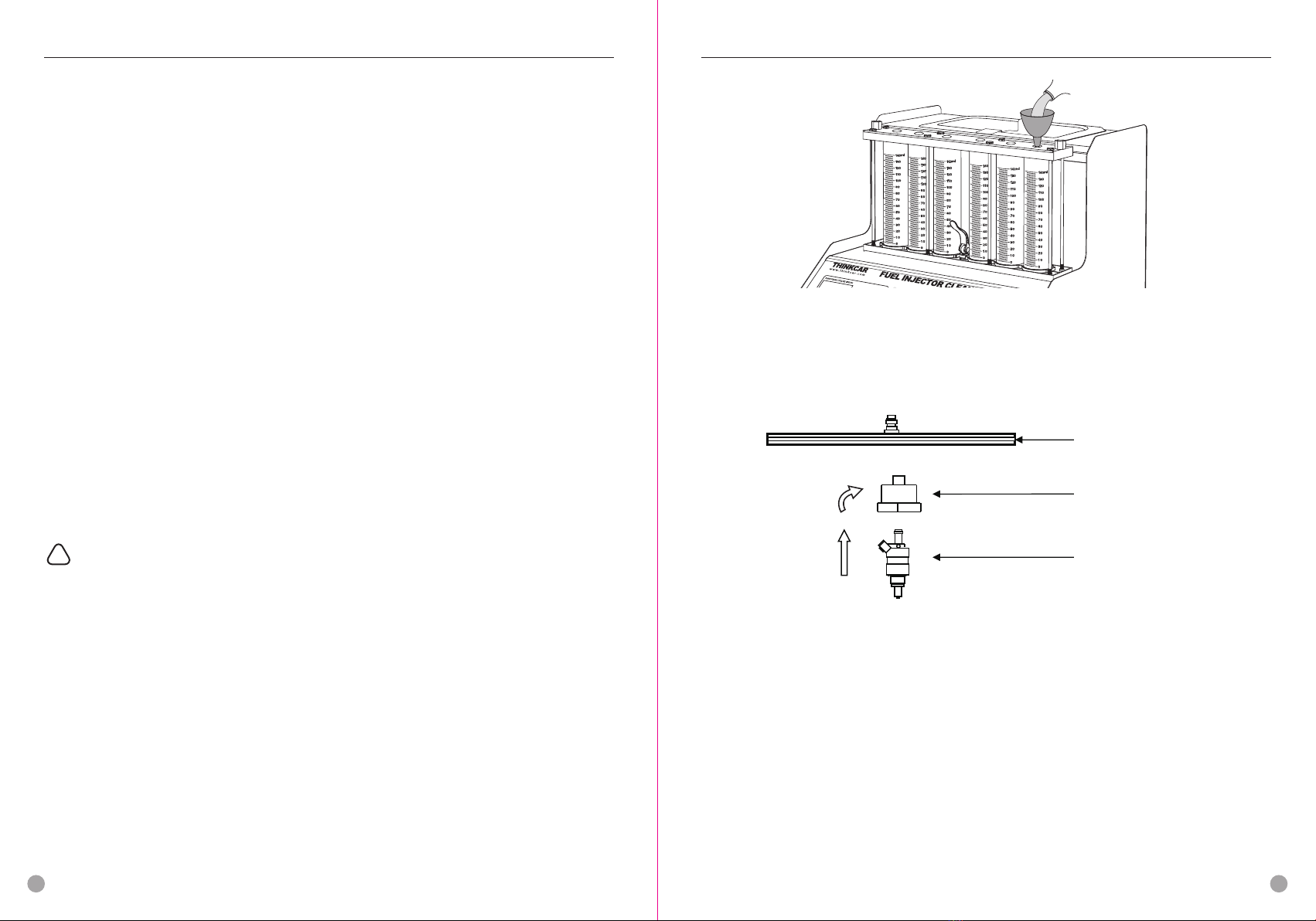
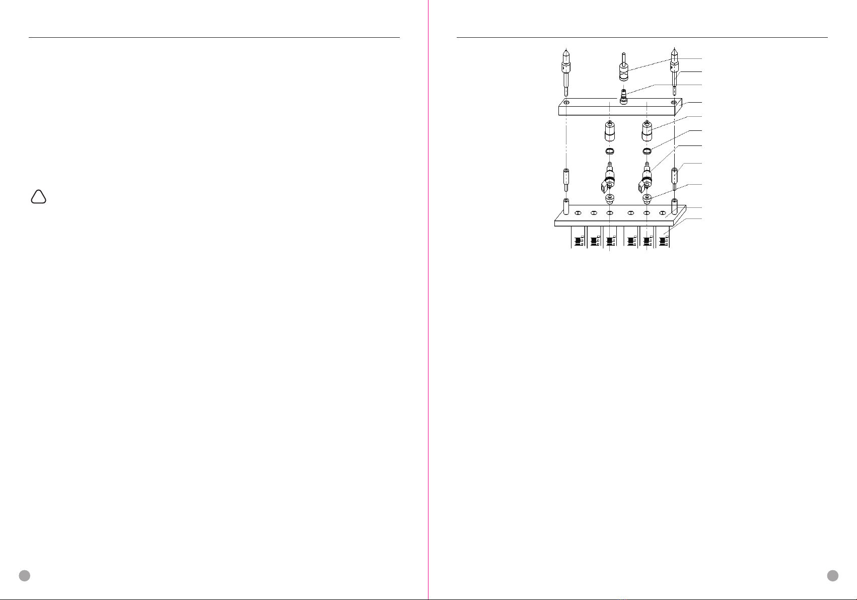
2) Reverse flushing installation of the top-injection nozzle.
2)Press 【START】key.
! Note:
· The system will set the fuel pressure, working time and pulse width systems automatically,
default time is 10s as one circulation period. User’s setting is unnecessary.
· The system will automatically simulate the working status and oil inject value of injector at
Idle Speed (700rpm), Medium Speed(4,500rpm) and High Speed (7,500rpm) working
condition in three times.
【07】Leak checking Test
1)Press the【+】and【-】key of the【FUNCTIONS/PULSE WIDTH】to select【07】
Leakage checking Test mode.
2)Press the【+】and【-】key of the【WORKING TIMES】to set time. (General setting is
one minute)
3)The following operation procedures is same with the 02 item.
! Note:
· Default pulse width system is 3 ms.
· Simulate the system pressure under 45 psi and test whether the injector has dripping.
【08】Idling Spray Value Test
1)Press the【+】and【-】key of the【FUNCTIONS/PULSE WIDTH】to select【08】Idling
Spray Value Test mode.
2) Press the【+】and【-】key of the【WORKING/INJECTING TIMES】to set times.
(General time is 2,000)
3)The following operation procedures is same with the 02 item.
! Note:
Simulate the working status and inject value under the idle speed of engine in several times.
THINKCAR THINKCAR
www.thinkcar.com www.thinkcar.com
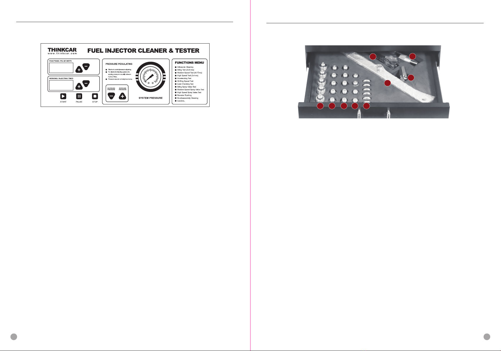
a. Select the upper recoil coupler (part 5) and the oil separator end cap to plug into the oil
separator (part 4) from the accessory box.
b. Put the recoil seal ring (part 6) on the fuel injection nozzle, (as shown in the figure), and
then install the fuel injection nozzle in the opposite direction. (The oil outlet is facing
upwards and the oil inlet is facing downwards)
c. Select the lower recoil coupler (part 9) from the accessory box and place it on the oil inlet of
the upper plate base (part 10).
d. Place the oil separator 4 and the horizontal end of the fuel injector on the lower recoil
coupler (part 9), and tighten the two ends with the extension rod 8 and the locking rod 2.
Ready to test.
4.3.2 Methods and steps
【11】Reverse Flushing
1) Connect the quick connector of the black oil outlet pipe on the machine with the male end
connector on the oil separator, and insert the fuel injector drive line.
2) Press the【+】and【-】key of 【FUNCTIONS/PULSE WIDTH】to select item 11 “Reverse
Flushing".
1
2
3
4
5
6
7
8
9
10
11
and return pipes of the original car to make it a loop. (Note: The fuel tank cap must be
opened, otherwise it is dangerous.)
5) Turn on the power of the equipment, press the item selection key to select item 12 “No
disassembly cleaning", and press the time adjustment key to adjust the time to 20
minutes-30 minutes.
6) Set the pressure according to the technical requirements of the car. (Generally,
0.25-0.3MPa is suitable to most car models).
7) Press 【START】key. Wait a few seconds to start the engine.
8) After engine starts, pour the disassembly-free cleaning liquid from any round hole above the
glass tube of the equipment. (The ratio of disassembly-free liquid and fuel is about 1:4.
Normally 1/2 bottle for four-cylinder cars, 3/4 bottle for six-cylinder cars, and 1 bottle for
eight-cylinder cars)
9)Adjust the car throttle. (1-10 minutes idling operation, 10-15 minutes medium and
high-speed operation, the rest of the time idling operation)
10)The time gradually decreases, and when it is reduced to 0, the system automatically
stops. Remove the non-dismantling device, and recovery the car's oil inlet and return pipes
and insurance.
11)Start the engine and run the car at high speed for 2-3 minutes to discharge the washed
carbon deposits in the exhaust pipe. At the same time, check whether there is leakage at
the oil pipe interface of the vehicle's fuel supply system.
! Note:
· The cleaning liquid is flammable, so pay attention to safety when cleaning.
· Before cleaning, it must be confirmed that all pipelines are connected well and there is no
leakage.
【13】Device Information
Remark the the equipment serial number and date of manufacture
If the model or function is changed, operate according the operation panel description.
5 Maintenance
5.1 Organization
1)Turn off the power and unplug the power.
2)Put all the even parts and free-disassembly connectors back into the accessory box for
storage.
3)Put the ultrasonic cleaning liquid back into the original bottle and seal it, and wipe the
equipment clean with a dry soft cloth.
4)If it is not used for a long time, open the oil drain screw at the bottom of the main unit and
put the test liquid in the oil tank back into the original bottle for sealed preservation.
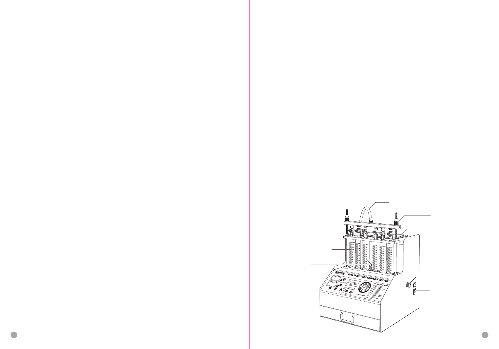
Schematic diagram of reverse flushing installation
1. Oil outlet pipe quick connector
2. Locking Lever
3. Oil Separator Joint
4. Oil rail
5. Upper Recoil Coupler
6. Recoil Seal Ring Φ24
7. Reverse installation of jacking oil injector
8. Extension Rod
9. Lower Recoil Coupler
10. Upper Plate Base
11. Measuring Cylinder
910