Table of Contents
1. BASIC INFORMATION 5
1.1. Who is the instruction for? 5
1.2. Installer qualifications required for the installation of an AirPack4h MVHR unit 5
2. DEVICE INSTALLATION 5
2.1. Mechanical assembly of the device. 5
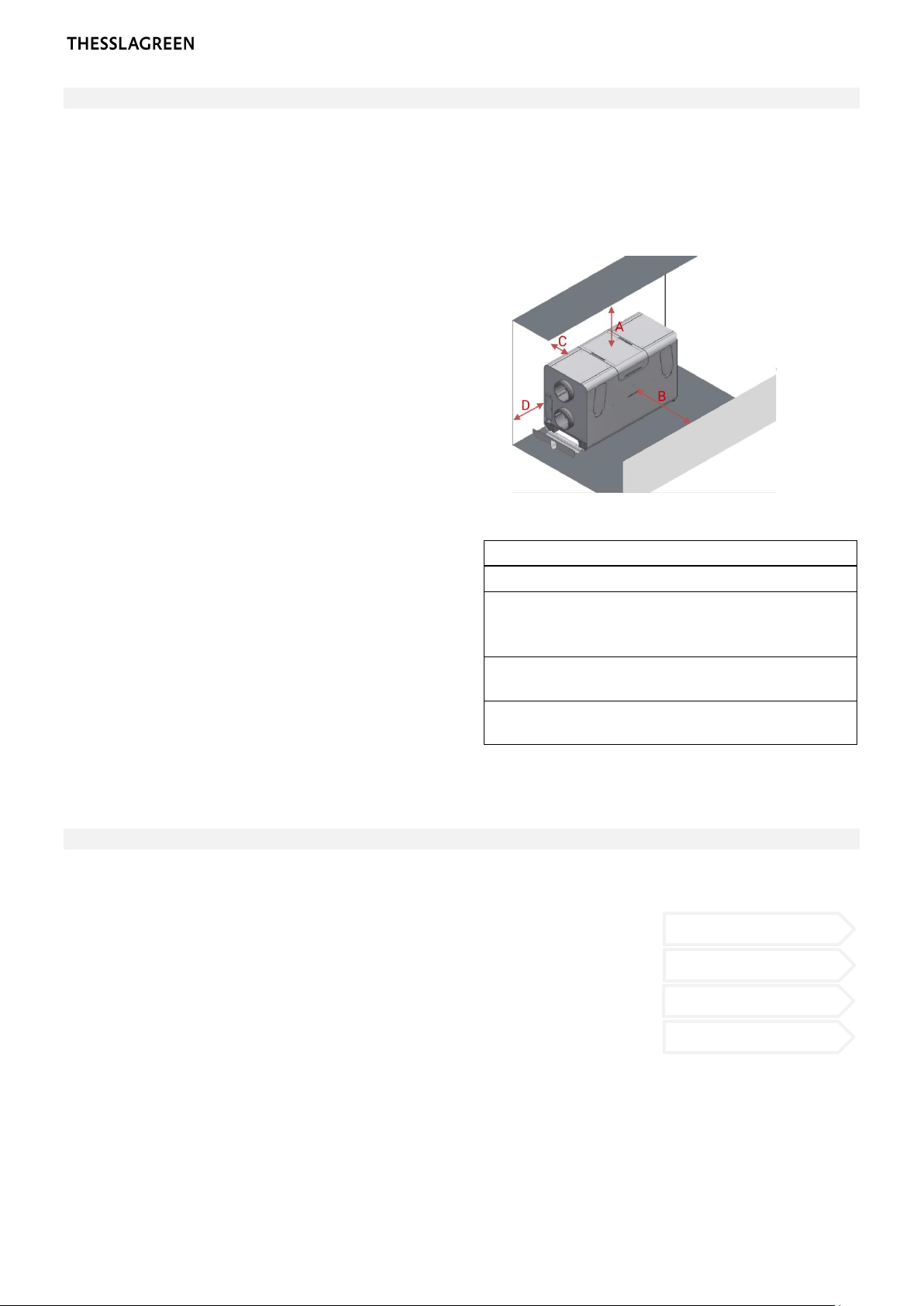
STEP 1 —Checking the technical conditions necessary for the operation of AirPack4h 6
STEP 2 —Selection of the mounting method 6
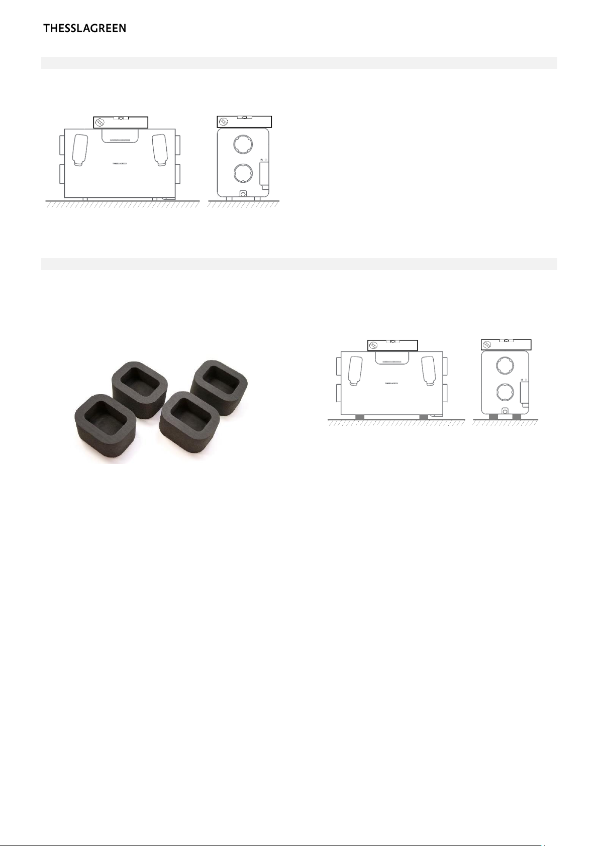
STEP 2A —Mounting AirPack4h on feet 7
STEP 2B —Mounting AirPack4h on feet with SoftBase4vibration isolation pads 7
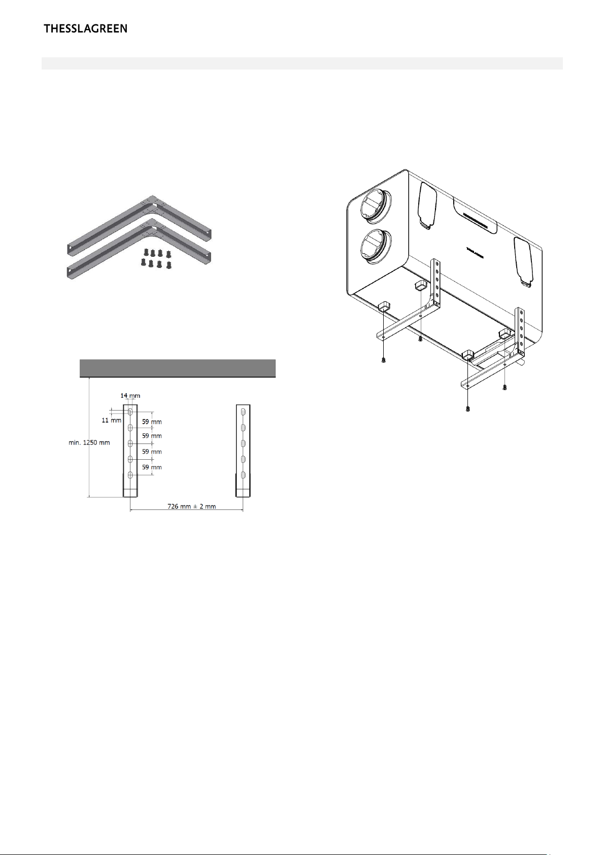
STEP 2C —Wall mounting AirPack4h on WallGrip4console 8
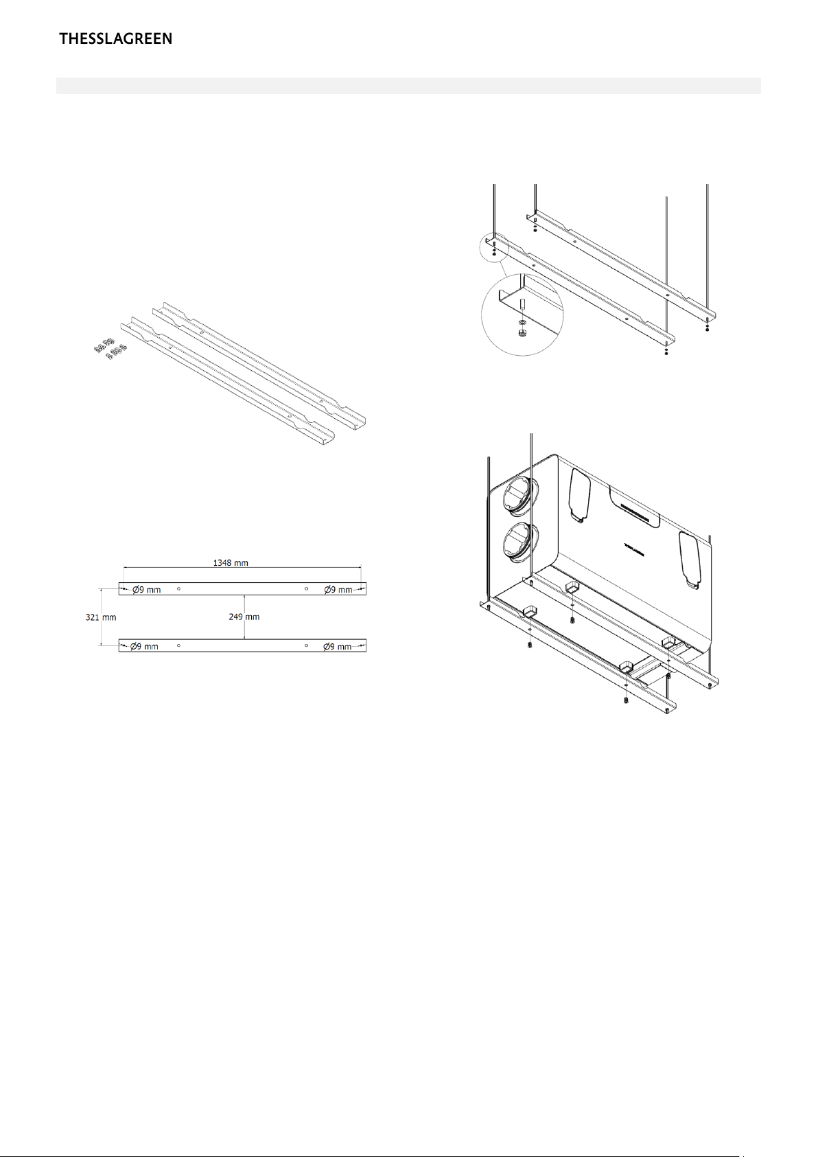
STEP 2D —Suspended mounting of AirPack4h on CeilingGrip4 console 9
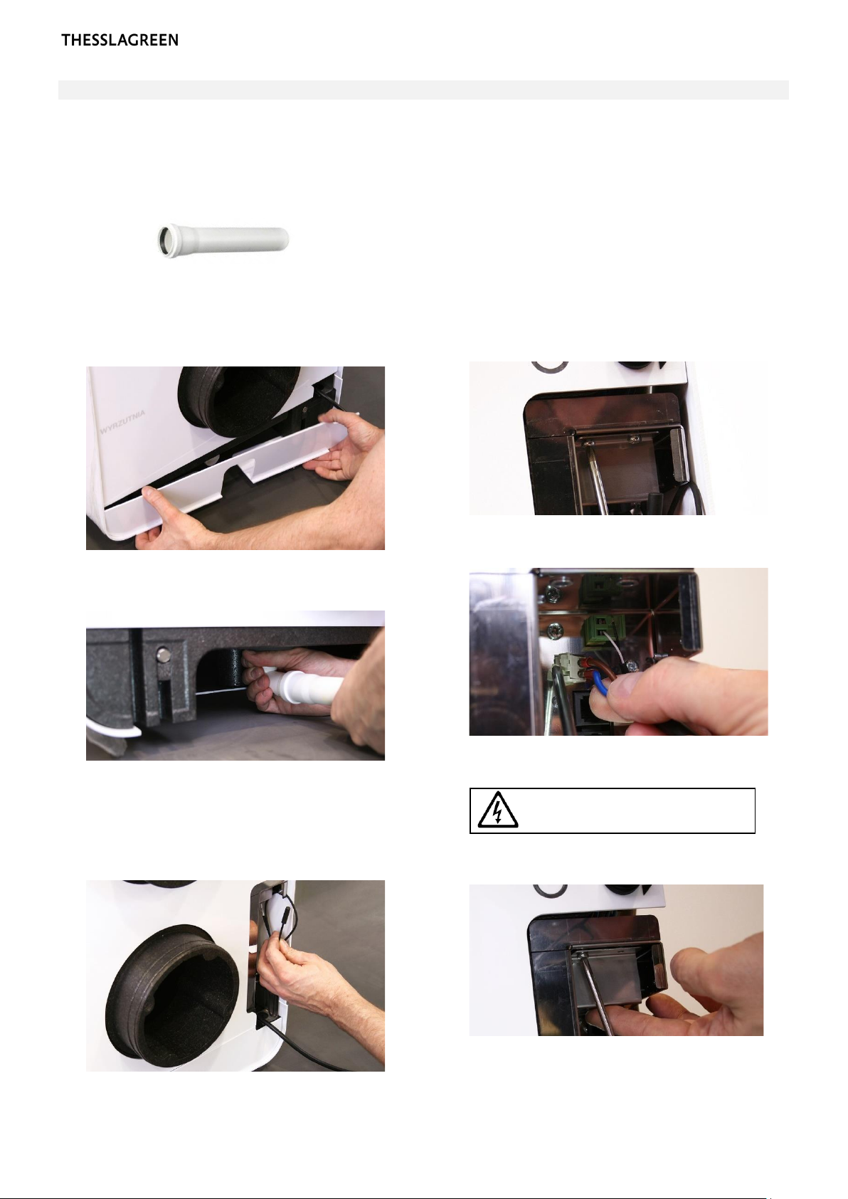
STEP 3 —Installation of the condensate drainage system 10
2.2. Installation of control panels 11
STEP 1 —Mounting of AirL+ control panel 11
STEP 2 —Mounting of the Air++ control panel 12
2.3. Extension of functionality based on the standard BASIC controller 13
STEP 2 —Installation of a hygrostat to start ventilation 14
STEP 3 —Installation of the air quality sensor to activate ventilation 15
2.4. Extension of functionality based on the EXPANSION module 16
STEP 1 —Preparation of the Expansion module 17
STEP 2 —Connecting the throttle controlling the operation of the GroundBox GT ground air
heat exchanger 17
STEP 3 —Connecting the throttle controlling the operation of a ground air heat exchanger
other than GroundBox GT 18
STEP 4 —Connecting the GWC ground-glycol heat exchanger 19
STEP 5 —Connecting the duct filter pressure switch 20
STEP 6 —Connecting the water heater 21
STEP 7 —Connecting the electric heater 22
STEP 8 —Connecting a smoothly controlled water or glycol cooler (0-10 V) with a regulation
valve 23
STEP 9 —Connecting the hysteresis controlled (ON-OFF) water or glycol cooler 24
STEP 10 —Connecting the HOOD function switch 25
STEP 11 —Connecting the FIREPLACE switch 25
STEP 12 —Connecting the FIRE ALARM control panel 26
STEP 13 —Connecting the alarm control panel 26
STEP 14 —Connecting the intake throttle actuator 27
STEP 15 —Connecting the throttle actuator of the air-outlet 27
STEP 16 —Connecting the Expansion module 28
3. STARTING THE DEVICE 29
3.1. The device is equipped with AirL+29
STEP 1 —Configuration using the AirL+panel 30
STEP 2 —Switching on using the AirL+panel 30
STEP 3 —Calibration of AirPack4 MVHR unit not equipped with CF module by using AirL+
panel 31
STEP 4 —Configuration of the AirPack4MVHR unit not equipped with the CF module using the
AirL+panel 32
STEP 5 —Configuration of the AirPack4 MVHR unit equipped with the CF module using the
AirL+panel 33
STEP 6 —Commisioning report 35
3.2. Urządzenie wyposażone w Air++ 36
STEP 1 —The device is equipped with Air++ 36
STEP 2 —Switching on the AirPack4MVHR unit using the Air++ panel 38
STEP 3 —Calibration of AirPack4MVHR unit not equipped with CF module by using AirL+
panel 39