THERMAL INTEGRATION XCEL Manuel utilisateur

Thermal Integration Ltd., 8 Curzon Road, Sudbury, Suffolk CO10 2XW
Te : 0845 2411441
XCEL HEAT BANKS
Installation Instructions
Rev03-09032018

2
Congratu ations on your purchase of an Xce Heat Bank therma store. The Xce is manufactured
in the UK from top qua ity materia s and meets a the atest re evant safety and constructiona
standards. The high grade aser cut and aser we ded Dup ex stain ess stee cy inder offers
exceptiona strength and corrosion resistance, backed by a ifetime guarantee. Insu ation eve s
exceed the atest requirements of Bui ding Regu ation Part L.
The Xce may be used with gas, oi or biomass boi ers, wood burners, so ar pane s, heat pumps,
e ectric heating e ements, or centra boi er systems. Two arge 1½” connections are provided for
connecting to wood burners and may be either pumped or on gravity circu ation. A arge 1m2 coi is
provided as standard for connection of so ar pane s. Three 2¼” connections are provided for
immersion heaters or retro-fit coi s. An additiona twenty two ¾” connections are provided for
pumped circuits, thermostats and sensors.
The Xcel’s DHW 160kW heat exchanger can heat mains water supplied at pressures between 0.1 and 10
bar, without the need for pressure reducing valves. Intermittent water supplies will not cause problems,
unless they are utilised for overheat protection.
The Xcel cylinder connects to a separate feed and expansion tank incorporating an open vent pipe, and
remains unpressurised without the need for safety discharge valves or annual maintenance. It is also
possible to connect the Xcel as a pressurised storage system, using the optionally supplied safety controls
in place of a feed tank, providing the Xcel is not connected to a uncontrolled heat source such as wood
burner or large solar array.
IMPORTANT Genera Requirements:
1. IN ORDER FOR GUARANTEES ON THIS SYSTEM TO START:
(a) THE INSTALLER MUST FILL IN THE FORM AT THE BACK OF THESE INSTRUCTIONS.
(b) THE OWNER OR OCCUPANT MUST FILL IN THE FORM AT THE BACK OF THESE INSTRUCTIONS AND
RETURN TO:
2. PLEASE READ THESE INSTRUCTIONS IN FULL BEFORE PROCEEDING WITH INSTALLATION.
3. THE XCEL SHOULD BE INSTALLED AND MAINTAINED BY A COMPETENT INSTALLER IN ACCORDANCE WITH G3
BUILDING REGULATION (ENGLAND AND WALES), P3 TECHNICAL STANDARD (SCOTLAND) OR P5 BUILDING
REGULATION (NORTHERN IRELAND), AS WELL AS THE WATER FITTING REGULATIONS (ENGLAND AND WALES)
OR WATER BYELAWS (SCOTLAND), AND I.E.E. WIRING REGULATIONS.
4. FOLLOWING INSTALLATION AND COMMISSIONING, THE OPERATION OF THE SYSTEM SHOULD BE EXPLAINED
TO THE AND THESE INSTRUCTIONS LEFT WITH THEM FOR FUTURE REFERENCE.
5. Read these instructions in conjunction with those of the primary heating appliances (boilers, wood burners etc.) before
attempting installation.
6. The Installer should tick sections in these instructions that have been applied to the final installation.
7. Do not attempt to lift the unit using the pre-fabricated pipework.
8. All pre-made connections should be checked & tightened prior to installation.
9. Connections in 22mm to the Heat Bank are provided by a combination of metric compression bosses, supplied with nuts
and olives, push-fit connections, and BSP threaded connections.
10. The stored water in the Heat Bank must be protected with a suitable chemical scale & corrosion inhibitor. It is important that
this is refreshed at suitable intervals to protect the store and all components.
11. The cylinder must be installed to allow access to all fitted components for maintenance purposes. This should include the
removal and replacement of Immersion Heaters.
12. The domestic hot water operates at mains pressure, therefore all pipework and fittings must be suitable for the maximum
pressure and temperature duty.
Thermal Integration Ltd., 8 Curzon Road, Sudbury, Suffolk CO10 2XW

3
Fu Mu ti Fue Schematic:
Standard Wiring:
1 Boiler Control
2 Central Heating
3 Secondary Circulation

4
E ectrica Supp ies:
1. The Xcel Heat Bank (when fitted with any controls) requires a 3 Amp, 230v AC power supply, via a fused switched spur.
2. Power supplies to boilers and other equipment that has wiring connections, should be taken from the wiring centre on the Xcel.
3. The Xcel can be optionally supplied with 3kW, 6kW, or 9kW electric elements, with up to three elements in total. Power supplies should
be as follows
(a) For 3kW elements, a 16 Amp , 230v AC power supply, via a double-pole wall switch. 2.5mm2 heat resistant cable to be used.
Standard immersion heater controllers may be used as required.
(b) For 6kW elements, a 30 Amp , 230v AC power supply, via a double-pole wall switch and double-pole contactor linked to
thermostats, low water switch, and timer (if required). 4mm2 heat resistant cable to be used.
(c) For 9kW elements, a 45 Amp , 230v AC power supply, via a double-pole wall switch and double-pole contactor linked to
thermostats, low water switch, and timer. 6mm2 heat resistant cable to be used.
4. RCD/RCBO protection should be provided on all immersion heater supplies.
5. All supplies must be earthed, as well as all connections to immersion heaters.
6. Do not turn on power supplies to the controls or immersion heaters until the system has been filled with water.
7. When connecting to immersion heaters, press the reset button on the fitted overheat thermostat, and check that control thermostats are
set to 75°C (unless the design of the system calls for different temperature settings).
Making Push-Fit Connections:
1. Any soldered joints in adjoining pipework should be made prior to connection to adjoining push-tit connections.
2. Cut tube square using a rotary pipe cutter - do not use a hacksaw to cut the tube.
3. Check that the end of the tube is free from burrs and sharp edges or damage will occur to the O-Ring seals.
4. Allow 27mm of pipe for insertion into the fitting plus 10mm of pipe to allow use of a disconnecting tool.
5. Insert the tube through the release collar of the fitting to rest against the grab ring.
6. Push the tube in firmly until it reaches the tube stop.

5
Feed and Expansion Tank:
1. Feed and Expansion tanks should be sized to allow for suitable expansion of all primary water,
equal to 4% of the entire system volume, including cylinder and pipework. Allowance should be
made for cold fill level, and a minimum of 30mm from position of overflow, and 60mm from cold
inlet position. As a rule of thumb, pick a header tank with a capacity of 10% of system volume.
2. Where wood burners are connected to system, a metal feed and expansion tank should be used,
along with a copper float on inlet valve.
3. An overflow must be connected that is rated to 100°C, continually falling, and is capable of
discharging the full failure flow rate of the inlet valve (with float removed). This must be checked
during commissioning.
4. Feed and Expansion Tanks should be insulated.
5. The vent pipe should be taken to a level 300mm higher than top of the F&E tank, before
connection through lid or into side at high level (30mm above overflow connection). If this is not
possible then it may be necessary to tee the cold feed into the vent
pipe (rather than the connection provided on the Xcel), via a return drop
of at least 300mm (see diagram).
6. Vent pipes must be continually rising from the Xcel. Horizontal runs
should have a slight incline.
7. Do not install separate vents, or cold feeds, at different points in a
system that shares flow. Any pumped flow will generate a pressure
difference along pipework, and this will cause circulation through the
F&E tank, heating it up, and mixing oxygen into the system,
accelerating system corrosion.
8. See Assembly X2009-19P for manually filled (no-discharge) systems.
9. Spare Parts
(a) Metal F&E Tank (400 litre systems) ........... 7067441
(b) Metal F&E Tank (800 litre systems) ........... 7067442
(c) Ball Float Valve
(d) Copper Float for float valve ....................... 7058763
(e) Tank Connector, 22mm Compression ....... 701022
Pressurised Storage Systems:
1. INSTALLATION AND MAINTENANCE OF PRESSURISED STORAGE SYSTEMS MUST BE DONE BY REGISTERED UNVENTED
PERSONS ONLY.
2. SYSTEMS MUST BE SERVICED ANUALLY, WITH ALL SAFETY VALVES TESTED.
3. SERVICING MUST BE RECORDED ON A LABEL SECURELY ATTACHED TO TORAGE UNIT.
4. SYSTEMS MUST NOT BE CONNECTED TO HEAT SOURCES (THAT CAN ACHIEVE > 90°C) WITHOUT THERMOSTATIC CONTROL,
OR WITHOUT THE FACILITY TO BE TURNED OFF VIA CONTROL THERMOSTATS, UNLESS SUITABLY APPROVED PROTECTION
HAVE BEEN PROVIDED.
5. DO NOT use O-Ring Seals on Immersion Heaters. If factory fitted then they should be replaced with PTFE string, and a fibre washer.
6. The following safety controls must be installed
(a) Expansion Vessel of size equal to, or greater than, 25% of total system volume, and having a pre-charge pressure between
0.9 and 1 bar.
(b) 2.5 bar Expansion Relief Valve, connected to a bottom (cold feed) connection on the Xcel, or adjoining pipework (without
possibility of isolation from the Xcel).
(c) 3 bar, 90°C Pressure and Temperature Relief Valve, connected directly to top (vent) connection on the Xcel.
(d) 1 bar RPZ (Reduced Pressure Zone) Automatic Filling Valve (requires discharge).
(e) Pressure Gauge and Temperature Gauge.
(f) Discharge pipe capable of removing the combined maximum discharge from all three safety valves.
7. Spare Parts
(a) Expansion Vessel, 80 litres ............................................................... 70101699
(b) Expansion Vessel, 80 litres. .............................................................. 70101700
(c) Expansion Vessel, 110 litres ............................................................. 7026118
(d) 2.5 bar Expansion Relief Valve ......................................................... 70674
(e) 3 bar, 90°C Pressure and Temperature Relief Valve ........................ 7069034
(f)
1 bar RPZ Automatic Filling Valve ..................................................... XVES
(g) Temperature and Pressure Gauge .................................................... 702308
(h) Temperature Gauge .......................................................................... 7014269
Straight Neck ...................................... 7068970
Swan Neck ......................................... 7059745

6
X2009-2: Mains Hot Water via P ate Heat Exchanger.
1. Please check that the maximum supply pressure does not exceed 6 bar, and if
necessary a Pressure Reducing Valve should be fitted onto the incoming
mains. Please ensure that all fittings and appliances connected to mains
supplies are rated at least 50% higher than supply pressure.
2. A Mains Isolating Valve must be fitted onto the incoming mains within the
cylinder cupboard within clear view.
3. A Y-Pattern Strainer (supplied loose) must be fitted onto the incoming mains.
The Y-Pattern Strainer should be fitted down-flow of the Isolating Valve in a
position to enable servicing.
4. In areas of hard water it is recommended that a Scale Inhibitor be fitted on the
incoming mains supply, and installed as per the manufacturers' instructions.
5. Although supply pressure may be as low as 0.1 bar, the flow rate performance
is relative to the supply pressures, and low supply pressures will result in poor
flow rates to taps.
6. A thermostatic mixing valve is supplied as standard for temperature limitation of
water supplied to outlets. This should be adjusted to users preference, and can
be locked to prevent tampering.
7. The circulating pump is factory set to speed 1. This can be turned up if flow
rates to hot taps need to be increased.
8. Pipework Connections
(a) Cold Mains In, 22mm.
(b) Hot Mains Out, 22mm.
9. Electrical
Connections factory
made.
10. Operation
(a) When a hot tap is opened, cold water passes
through the flow switch, plate heat exchanger and
thermostatic valve.
(b) The flow switch passes a live signal to the
circulating pump via the relay.
(c) Hot water is pumped into the heat exchanger from
the top of the Xcel, heating up the mains water
supplied to taps.
(d) When the tap is shut, the flow switch removes live
feed from the pump
11. Spare Parts
(a) Thermostatic Mixing Valve, 22mm .............. 70200015
(b) Thermostatic Mixing Valve, 28mm .............. 70200004
(c) Circulating Pump ........................................ 70200226
(d) Flow Switch (Must be fitted with Relay)..... 702307
When connecting the cold mains water supply to the flow switch, care must be taken how the work is done.
It is important that the pipework is installed such that the body of the flow switch sits vertically to ensure
that it operates satisfactorily. If it sits out of line from the vertical, it may cause the switch to activate inconsistently
and fail to run the heat exchanger pump
(e) Relay............................................................ 7069689

7
X2009-5: Direct Boi er Connection, GX System, 35kW.
See Also 11B/12B (Pumps) and 6,7 (Thermostats)
1. Suitable for connection of boilers up to 35kW output.
2. If output of boiler exceeds 35kW, assembly X2009-5A is required
instead.
3. The lower return connection from the Xcel to the Boiler is taken from
above the solar coil as standard. To enable the boiler to heat the entire
store (including solar section), then the return connection needs to be
reconnected lower down, and cylinder thermostats need lowering.
4. It assists in commissioning, and fault-finding, to install temperature
gauges on boiler flow and return pipes.
5. If the Xcel is installed as a vented system, and the boiler is only
suitable for pressurised systems, then a plate heat exchanger will need
to be installed to isolate boiler from vented storage system.
6. The circulating pump is factory set to speed 3. This can be adjusted to
obtain a temperature drop across boiler of 15 to 20°C.
7. Return temperature to boiler should ideally be 55°C, with an 18°C
temperature rise, to achieve a 73°C flow temperature.
8. Boiler control thermostat should generally be left on maximum.
9. Pipework Connections
(a) Return top Boiler, 28mm.
(b) Flow from Boiler, 28mm.
10. Electrical Connections (Single Thermostat)
11. Operation
(a) When cylinder thermostats call for heat, a live feed is provided to boiler,
and boiler pump.
(b) The boiler fires, and water is re-circulated by the return mixer from the top
of the Xcel, through the boiler, and back to the top of the Xcel.
(c) Once the top of the Xcel reaches > 55°C, the return mixer starts drawing
from the base connection to the Xcel, to regulate return temperature.
(d) Xcel heats up from the top-downwards, until cylinder thermostats are
satisfied, and live feed to boiler is removed.
(e) Boiler pump may keep running for a short period following boiler turn-off.
12. Spare Parts
(a) Return Mixing Valve, 28mm ............................. 70200001
(b) Circulating Pump [X2009-11B] ....................... 70200226
(c) High Flow Circulating Pump [X2009-12B] ...... 70200124
8
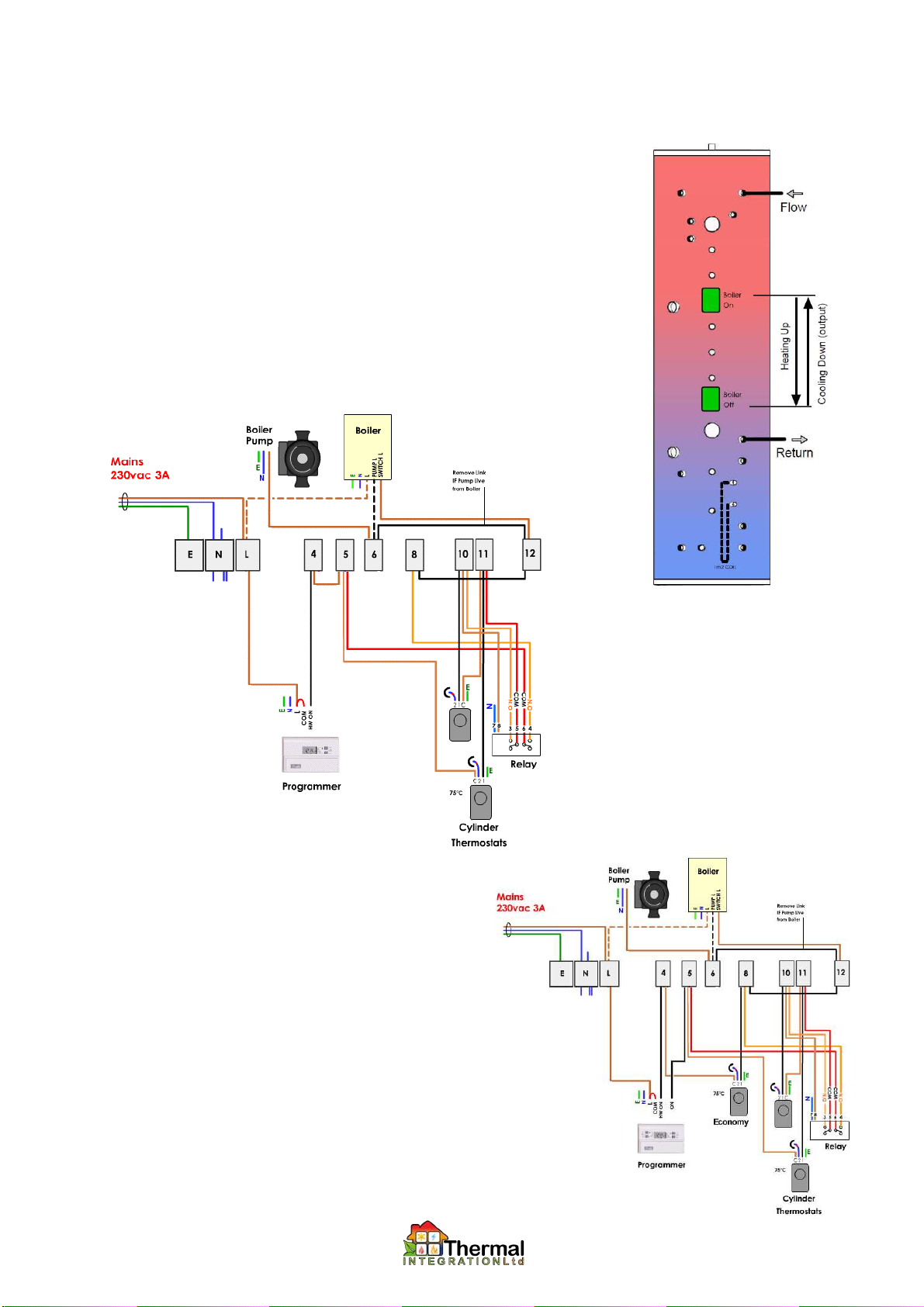
X2009-7: Thermostat and Re ay for Buffering Boi er Input.
X2009-8: Thermostat for Boi er Contro (economy mode). (see X2009-18A)
1. The use of two thermostats linked with a relay allows the thermostats to act as a latch, with one
thermostat acting as the switch on, and the other as the switch off. This is used to hold off firing
of the boiler until there is a known volume of water at a low enough temperature to call for the
boiler to fire.
2. Once fired, the boiler will continue to fire until the off thermostat is satisfied.
3. Additional cylinder thermostats can provide reheating to set positions on the store (assuming
top-down reheating). Thermostats located at the top of the Xcel can provide an economy mode,
heating up small quantities of hot water for low-medium hot water demand. Thermostats located
at base of the Xcel can provide a heavy demand mode, where the entire volume of the store is
heated.
4. Additional switching will be required for each thermostat used, either by a wall mounted switch,
or using a timer or programmer.
5. Electrical Connections (X2009-7 only)
6. Electrical Connections (X2009-7 and -8)
7. Spare Parts
(a) Danfoss Randall ITC 100 thermostat .................. 7025442
(b) Relay .................................................................... 702315
COM
Volt-Free Call
Volt-Free Call
COM
Volt-Free Call
Volt-Free Call
1 5 3 4
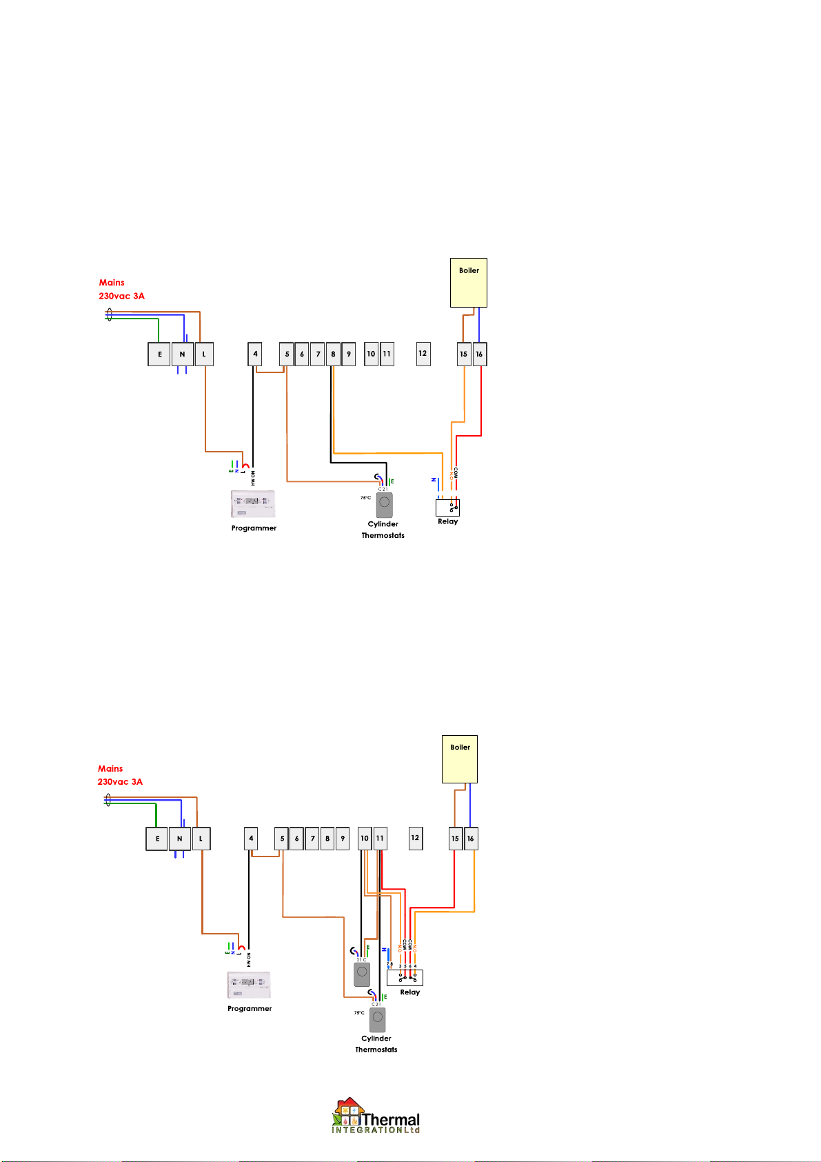
Note: The preceding thermostat options (X2009-5; -7; -8) are intended to provide a switched live 230Vac signal to call a
gas / oil fired boiler, or similar heat source, to fire. In the case of appliances that required a volt-free / clean contact call
(e.g. MCZ pellet boilers and stoves), the call out from the cylinder thermostat/s must be passed via a relay. This can be
retrospectively fitted during installation (part no: X2009-2 RELAY can be obtained for this purpose).
Alternatively, The following pre-wired thermostat options provide this facility if the unit has been ordered with them:
X2009-8P-VF: Single Thermostat for Volt-Free Boiler Input
1. Pre-wired single thermostat, suitable for use with any boiler that requires a volt-free / clean contact call to fire.
2. Comprises pre-wired thermostat only: Does not include pre-plumbed GX assembly.
3. Wiring includes a single pole relay that gives volt-fee switched call for heat.
4. Electrical connections:
X2009-7-VF: Thermostat and Relay for Volt-Free Buffering Boiler Input
1. Pre-wired twin thermostats suitable for use with any boiler that requires a volt-fee / clean contact call to fire
2. Comprises pre-wired thermostats only: does not include pre-plumbed GX assembly.
3. Wiring includes a double pole relay that provides latching circuit for buffered operation (as per X2009-7), and also gives
volt-free switched call for heat.
4. Mode of operation is as per X2009-7
5. Electrical connections:
9

10
X2009-9: Overheat Thermostat.
1. The overheat thermostat is wired to pass a live to a central heating pump to initiate central heating once the stored water reaches 90°C,
thereby cooling the store and preventing overheating due to continued heat input from wood burners or solar panels.
2.
If motorised valves or actuators are fitted on heating circuits, then the overheat thermostat must be wired so as to open the appropriate
valve(s) and initiate the circulation pump for the overheat dump circuit.
3. Ensure that the dump heating circuit is capable of removing enough heat from the system. This will depend on the type of appliance that
overheat protection is provided for. In the case of wood burners without thermostatic control, this can be between 3 and 30kW depending
on model and type of fuel used.
4. Ensure that any fitted radiator thermostats or room thermostats do not prevent transfer of heat, even when rooms are up to temperature.
Some radiators may have to be left without thermostatic valves.
5. Room thermostats are by-passed as shown in wiring diagram below.
6. The temperature setting on the overheat thermostat may be lowered if it is desirable to have central heating start automatically when the
store reaches a specified temperature.
7.
When dumping heat into an underfloor heating system, it will be necessary to integrate with the type of underfloor heating controls that
are used. It is generally necessary to simulate both a call for heating and short-circuit the room thermostats of the zones to be dumped to,
and may require the use of additional relays. For further help, please contact the TI technical department, providing detailed
information on the UFH wiring.
8. This option is often used in conjunction with Option X2009-13 Power-free overheat protection via discharge.
9. Electrical Connections (Standard Radiator Circuit with Programmable Room Thermostat and Overheat)
10. Spare Parts
(a) Danfoss Randall ITC 100 thermostat .................. 7025442
Table des matières
Manuels Chauffage populaires d'autres marques

oventrop
oventrop Regucor Series Manuel utilisateur

Blaze King
Blaze King CLARITY CL2118.IPI.1 Manuel utilisateur

ELMEKO
ELMEKO ML 150 Manuel utilisateur

BN Thermic
BN Thermic 830T Manuel utilisateur

KING
KING K Series Mode d’emploi

Empire Comfort Systems
Empire Comfort Systems RH-50-5 Guide de démarrage rapide


Empire Heating Systems
Empire Heating Systems WCC65 Manuel utilisateur

Wetekom
Wetekom 92 86 43 Manuel utilisateur

Desa
Desa SPC170-F Manuel utilisateur

Watlow
Watlow Watrod Electric Tubular Heaters Manuel utilisateur

Haverland
Haverland ECO-DRY GPS Series Manuel de la liste des pièces

Stelpro
Stelpro ASILVC2060 Series Manuel utilisateur