Thales mPLS62 Manuel utilisateur

Getting Started with LTE Modem
Cards
User Guide
Version: 03
DocId: mPLS62_mPLS8_mPLAS9_mPLSx3_ug_startup_v03

GENERAL NOTE
THIS DOCUMENT CONTAINS INFORMATION ON THALES PRODUCTS. THALES RESERVES THE
RIGHT TO MAKE CHANGES TO THE PRODUCTS DESCRIBED HEREIN. THE SPECIFICATIONS IN
THIS DOCUMENT ARE SUBJECT TO CHANGE AT THE DISCRETION OF THALES. THE PRODUCT
AND THIS DOCUMENT ARE PROVIDED ON AN "AS IS" BASIS ONLY AND MAY CONTAIN DEFICIEN-
CIES OR INADEQUACIES. THALES DOES NOT ASSUME ANY LIABILITY FOR INFORMATION PRO-
VIDED IN THE DOCUMENT OR ARISING OUT OF THE APPLICATION OR USE OF ANY PRODUCT
DESCRIBED HEREIN.
THALES GRANTS A NON-EXCLUSIVE RIGHT TO USE THE DOCUMENT. THE RECIPIENT SHALL
NOT COPY, MODIFY, DISCLOSE OR REPRODUCE THE DOCUMENT EXCEPT AS SPECIFICALLY
AUTHORIZED BY THALES.
Copyright © 2021, THALES DIS AIS Deutschland GmbH
Trademark Notice
Thales, the Thales logo, are trademarks and service marks of Thales and are registered in certain coun-
tries.
PCI-SIG®, PCIe®and the PCI Express®design mark are registered trademarks and/or service marks of
PCI-SIG.
Microsoft and Windows are either registered trademarks or trademarks of Microsoft Corporation in the
United States and/or other countries.
All other registered trademarks or trademarks mentioned in this document are property of their respective
owners.
tmPLS62_mPLS8_mPLAS9_mPLSx3_ug_startup_v03 2021-03-15
Public / Released
Getting Started with LTE Modem Cards
2
Page 2 of 21
User Guide: Getting Started with LTE Modem Cards
Version: 03
Date: 2021-03-15
DocId:
mPLS62_mPLS8_mPLAS9_mPLSx3_ug_startup_v03
Status Public / Released

Getting Started with LTE Modem Cards
Contents
21
tmPLS62_mPLS8_mPLAS9_mPLSx3_ug_startup_v03 2021-03-15
Public / Released
Page 3 of 21
Contents
0 Document History ...................................................................................................... 4
1 Introduction ................................................................................................................. 5
1.1 Supported Products ........................................................................................... 5
1.2 Related Documents ........................................................................................... 5
2 Getting Started with LTE Modem Cards ................................................................... 6
2.1 Technical Requirements for Using LTE Modem Cards...................................... 6
2.2 Connecting the LTE Modem Card to the LTE Modem Card Adapter Board...... 7
2.3 Start Up the Module ......................................................................................... 10
3 Appendix.................................................................................................................... 15
3.1 LTE Modem Card Adapter Board .................................................................... 15
3.1.1 Package content ................................................................................. 15
3.1.2 LTE Modem Card Adapter Board Description .................................... 15
3.1.3 LTE Modem Card Adapter Board Schematic...................................... 16
3.2 Digital Audio Interface (mPLSx3 only) ............................................................. 18
3.2.1 Wideband Audio Codec Adapter......................................................... 19
3.2.2 Audio Bridge ....................................................................................... 20

Getting Started with LTE Modem Cards
0 Document History
4
tmPLS62_mPLS8_mPLAS9_mPLSx3_ug_startup_v03 2021-03-15
Public / Released
Page 4 of 21
0 Document History
New document: "Getting Started with LTE Modem Cards" Version 03
Previous document: "Getting Started with LTE Modem Cards" Version 02
New document: "Getting Started with LTE Modem Cards" Version 02
Previous document: "Getting Started with LTE Modem Cards" Version 01
New document: "Getting Started with LTE Modem Cards" Version 01
Chapter What is new
-- new document layout
throughout
document
added product family PLSx3
2.2 Revised Table 2
3.2 New chapter Digital Audio Interface (mPLSx3 only)
Chapter What is new
3.1.2 Revised Figure 8
3.1.3 Revised Figure 9
Chapter What is new
--- Initial document setup.

Getting Started with LTE Modem Cards
1 Introduction
20
tmPLS62_mPLS8_mPLAS9_mPLSx3_ug_startup_v03 2021-03-15
Public / Released
Page 5 of 21
1 Introduction
This document describes a ready-to-use development and test environment for the Thales LTE
Modem Cards.
The development and test environment comprises the following hardware components
• LTE Modem Card mPLAS9-W, mPLAS9-X, mPLS8-US, mPLS8-E, mPLS62-W or mPLSx3
• LTE Modem Card Adapter Board
The purpose of this document1is to guide you through the process of connecting the hardware,
installing the supplied drivers on a Microsoft®Windows 7 or Microsoft®Windows 8 system and
getting started with LTE Modem Card.
1.1 Supported Products
This document applies to the following Thales LTE Modem cards:
•Cinterion
®mPLAS9-W
•Cinterion
®mPLAS9-X
•Cinterion
®mPLS8-US
•Cinterion
®mPLS8-E
•Cinterion
®mPLS62-W
•Cinterion
®mPLS63-W A
•Cinterion
®mPLS63-W B
•Cinterion
®mPLS83-W A
•Cinterion
®mPLS83-W B
•Cinterion
®mPLS83-X A
LTE Modem Card in this document refers to all of the above mentioned product variants. mPLSx3
is used for the 5 variants mPLS63-W A, mPLS63-W B, mPLS83-W A, mPLS83-W B and
mPLS83-X A. Where necessary a note is made to differentiate between these product variants.
1.2 Related Documents
[1] PLAS9-W AT Command Set
PLAS9-X AT Command Set
PLS8-US AT Command Set
PLS8-E AT Command Set
PLS62-W AT Command Set
PLS63-W AT Command Set
PLS83-W AT Command Set
PLS83-X AT Command Set
[2] mPLAS9-W Hardware Interface Description
mPLAS9-X Hardware Interface Description
mPLS8-US Hardware Interface Description
mPLS8-E Hardware Interface Description
mPLS62-W Hardware Interface Description
mPLSx3 Hardware Interface Description
[3] Audio Codec Adapter Setup for Cinterion®Modules
1. The document is effective only if listed in the appropriate Release Notes as part of the technical docu-
mentation delivered with your Thales product.

Getting Started with LTE Modem Cards
2 Getting Started with LTE Modem Cards
20
tmPLS62_mPLS8_mPLAS9_mPLSx3_ug_startup_v03 2021-03-15
Public / Released
Page 6 of 21
2 Getting Started with LTE Modem Cards
2.1 Technical Requirements for Using LTE Modem Cards
• LTE Modem Card (for details see Figure 1 and [2])2
• corresponding driver package (USB)
• Computer running Windows 7 or Windows 8, USB 2.0 High Speed compatible
• Local administrator privileges on the particular Windows computer to install and uninstall
the drivers
• LTE Modem Card Adapter Board (for details see Section 3.1)
• Accessories:
- Two (mPLAS9-W, mPLAS9-X, mPLS62-W) or three (mPLS8-US, mPLS8-E, mPLSx3)
short 50 Ohms RF adapter cables - 2xRF and 1xGNSS, with ultra-miniature U.FL SMT
connectors to connect the appropriate U-FL connectors on the LTE Modem Card Adapter
Board (supplied by Thales)
- Two external 50 Ohms RF antennas - GSM/UMTS/LTE main antenna and UMTS/LTE
Rx diversity/MIMO antenna, with SMA connector to connect the SMA connector on the
LTE Modem Card Adapter Board (supplied by Thales)
-mPLS8-US, mPLS8-E and mPLSx3 only: One GNSS antenna with SMA connector to
connect the SMA connector on the LTE Modem Card Adapter Board (not supplied by
Thales).
- 3.3V power supply applied at the LTE Modem Card Adapter Board for powering up the
LTE Modem Card Adapter Board and the connected LTE Modem card (not supplied by
Thales)
- USB cable with mini-USB plug (supplied by Thales)
• Appropriate application for controlling the module from within a PC’s operating system. For
Windows, e.g. Windows Hyperterminal
• (U)SIM from a GSM/UMTS/LTE network provider
2. For ordering information see [2].

Getting Started with LTE Modem Cards
2.2 Connecting the LTE Modem Card to the LTE Modem Card Adapter Board
20
tmPLS62_mPLS8_mPLAS9_mPLSx3_ug_startup_v03 2021-03-15
Public / Released
Page 7 of 21
2.2 Connecting the LTE Modem Card to the LTE Modem Card
Adapter Board
To properly connect the LTE Modem Card and all accessories to the LTE Modem Card Adapter
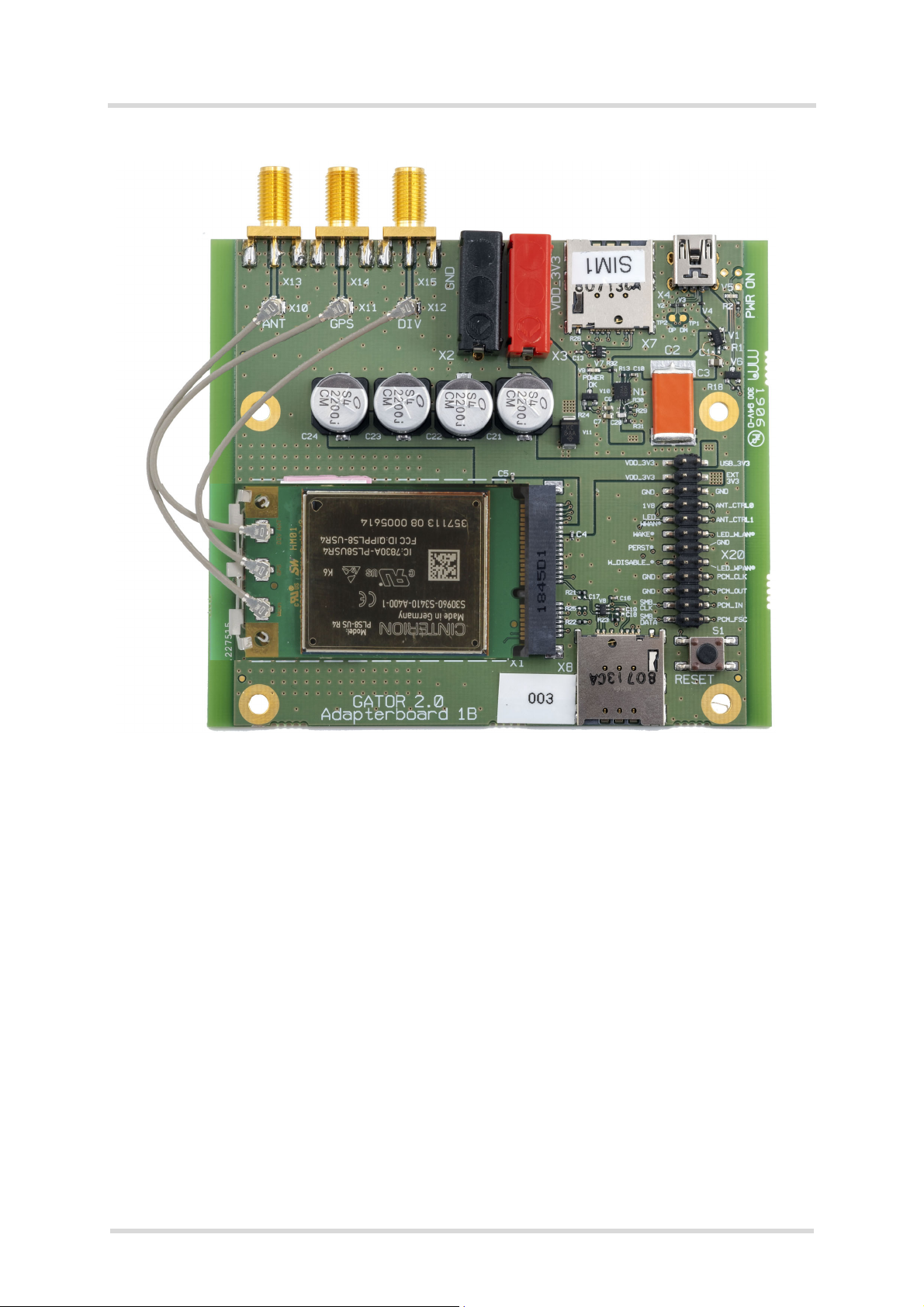
Board please complete the steps listed below. The complete setup with the LTE Modem Card
mounted onto the LTE Modem Card Adapter Board is shown in Figure 2.
• Ensure that all jumpers on the LTE Modem Card Adapter Board are set to their default posi-
tions as shown in Figure 8 and Table 1.
• Screw the external GSM/UMTS/LTE main and Rx diversity/MIMO antennas to the appro-
priate SMA connectors on the LTE Modem Card Adapter Board (X13 and X14).
•mPLS8-US, mPLS8-E and mPLSx3 only: Screw the external GNSS Antenna to the SMA
Connector on the LTE Modem Card Adapter Board (X15).
• Plug the USB 2.0 Mini-connector of the USB cable to the Mini USB jack at the LTE Modem
Card Adapter Board (X4). The other end of the USB cable connects to a PC.
• Insert the LTE Modem Card into the connector X1 on the LTE Modem Card Adapter Board.
• Connect the U.FL SMT connectors for the GSM/UMTS/LTE main and Rx diversity/MIMO
antennas on the LTE Modem Card Adapter Board (X10 and X11) to the matching U.FL SMT
connectors on the LTE Modem Card.
•mPLS8-US, mPLS8-E and mPLSx3 only: Connect the U.FL SMT connector for the GNSS
antenna on the LTE Modem Card Adapter Board (X12) to the matching U.FL SMT connec-
tor on the LTE Modem Card.
• Insert the (U)SIM card into the card reader labeled X8.
• If not powered over USB make sure that the power supply adapter is switched to 3V3 Volts
and place the Jumper on X20 on the LTE Modem Card Adapter Board to PIN 3 and PIN 4
(see Table 1). Connect the power cables to the red (X3 = 3V3) and black (X2 = Ground)
connectors of the LTE Modem Card Adapter Board.
After connecting the LTE Modem Card with the LTE Modem Card Adapter Board, the LTE Mo-
dem Card can be switched on. The initial startup and possible USB driver installation are de-
scribed in Section 2.3.

Getting Started with LTE Modem Cards
2.2 Connecting the LTE Modem Card to the LTE Modem Card Adapter Board
20
tmPLS62_mPLS8_mPLAS9_mPLSx3_ug_startup_v03 2021-03-15
Public / Released
Page 8 of 21
Figure 1: LTE Modem Card
Bottom side
Top side
Antenna U.FL-R SMT connectors:
Main antenna Rx Diversity/MIMO antenna
Cinterion®SMT module
GPS antenna1)
PCI Express® Mini Card system connector
PIN 1 PIN 51 PIN 2 PIN 52
1) GPS Antenna only supported by mPLS8-E, mPLS8-US and mPLSx3 LTE Modem Cards

Getting Started with LTE Modem Cards
2.3 Start Up the Module
20
tmPLS62_mPLS8_mPLAS9_mPLSx3_ug_startup_v03 2021-03-15
Public / Released
Page 10 of 21
2.3 Start Up the Module
After connecting the LTE Modem Card to the LTE Modem Card Adapter Board as described in
Section 2.2, the module can be switched on.
Note: The USB drivers provided by Thales need to be available. Copy the supplied driver files
to a folder on the Windows computer. Be sure to use the latest USB driver software supplied
by Thales.
• Start the Windows PC.
• switch on the external 3.3V power supply, when the power supply of the LTE Modem Card
Adapter Board will be not done via USB.
• If the USB cable was plugged as described above, and the USB drivers provided by Thales
were not yet installed on the computer, you will be prompted to install them:
- On Windows 7 or Windows 8, wait a few seconds until all USB devices show up as "CDC
Serial" in the Windows Device Manager under "Other Devices". Then - from top to bottom
- right-click each "CDC Serial" device, select the option "Update Driver Software...",
browse to the folder you copied the Thales USB drivers to, and select this folder to update
the driver software from.
For mPLS62-W and mPLSx3 there will “PLSx” devices shown, which have to be
updated. Then - from top to bottom - right-click each PLSx” device, select the option
"Update Driver Software...", browse to the folder you copied the Thales USB drivers to,
and select this folder to update the driver software from.
- In any case, cancel any Windows instructions to update the software automatically. For
each USB device take care to browse to the folder containing the unzipped driver soft-
ware.
After successful USB driver installation the installed USB devices are listed in the Windows
Device Manager under "Modems", "Network adapters" and "Ports (COM & LPT)" as shown
in Figure 3 for mPLS8-E/US, in Figure 4 for mPLAS9-W/X, in Figure 5 for mPLS62-W and
in Figure 6 for mPLSx3.
Figure 3: Installed USB devices mPLS8-E/US
Ce manuel convient aux modèles suivants
3
Table des matières
Autres manuels Thales Carte réseau
Manuels Carte réseau populaires d'autres marques

3Com
3Com EtherLink 3C509B Manuel utilisateur

TRENDnet
TRENDnet TEG-PCITX Manuel utilisateur

Cisco
Cisco MC16E Manuel utilisateur

Delta Electronics
Delta Electronics Braking Modules VFDB Series Manuel utilisateur

TwinMOS
TwinMOS Booming Manuel utilisateur

Dialogic
Dialogic Media Board DM/V1200BTEPEQ Manuel utilisateur

Buffalo
Buffalo AirStation WLI-PCM-L11GP Manuel utilisateur

National Instruments
National Instruments NI 9234 Manuel utilisateur

Hama
Hama 49276 Manuel utilisateur

Linksys
Linksys WCF54G - Wireless-G Compact Flash Card Manuel d'utilisation

Compaq
Compaq Wireless LAN 100 Manuel utilisateur

Bose
Bose PowerMatch Dante Manuel utilisateur