Premier OP16 Installation Manual Installation
INS186 7
Connecting Output Expanders
Before connecting output expanders, isolate ALL power from the control panel (AC
Mains and Battery). Do not continue if there is power still present on the control panel.
Connecting an expander with power still present on the control panel may
damage the expander or control panel and invalidate any warranty.
Output expanders, keypads and zone expanders are all connected to the same
network terminals located at the bottom left hand corner of the control panel and may
be connected serially (daisy chain), in parallel (star) or any combination of the two.
A maximum of 4 output expanders, 8 keypads and 8 zone expanders can be
connected to each network.
Whenever new devices are connected to the network, they must be confirmed
onto the system using the ‘Confirm Devices’ menu option. For details on
confirming devices please refer to the Premier 24/48/88/168/640 Installation
Manual.
Wiring the Network
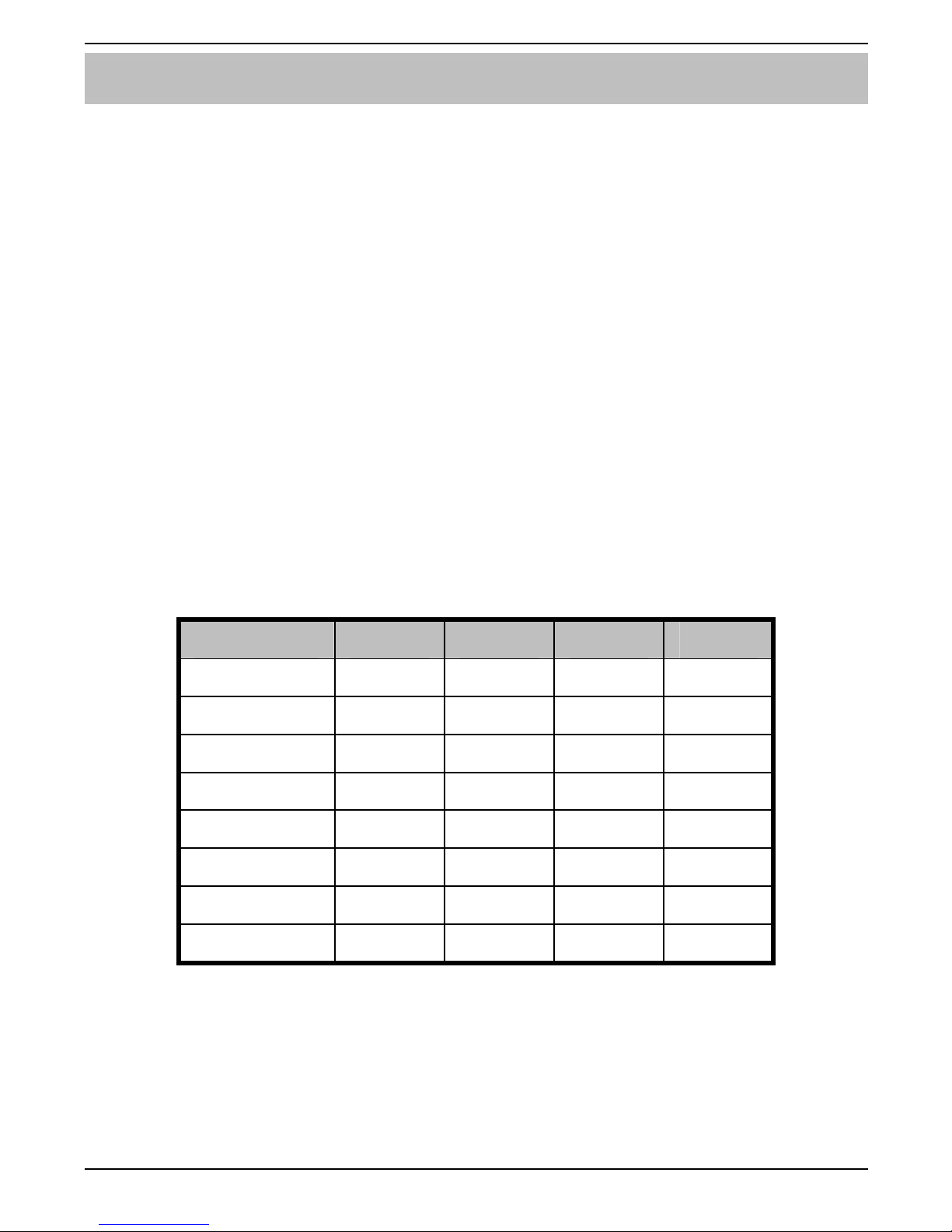
The networks are made up of four terminals incorporating power and data. To
ensure correct operation, all four terminals on the device must be connected to the
corresponding terminals on the control panel or previous device. The table below
shows each terminal and its description:
Terminal Description
+ +12V Supply
- 0V Supply
T Transmit Data
R Receive Data
Output expanders can be connected using 4-core cable. However, it is
recommended that 6 or 8-core cable is used as the spare cores can be used to
‘Double Up’ on the power connections if needed.
Standard 7/0.2 alarm cable can be used for most installations. However, under
certain conditions it may be necessary to use screened cable.