RA 100 Concrete
Model 1.0390
10
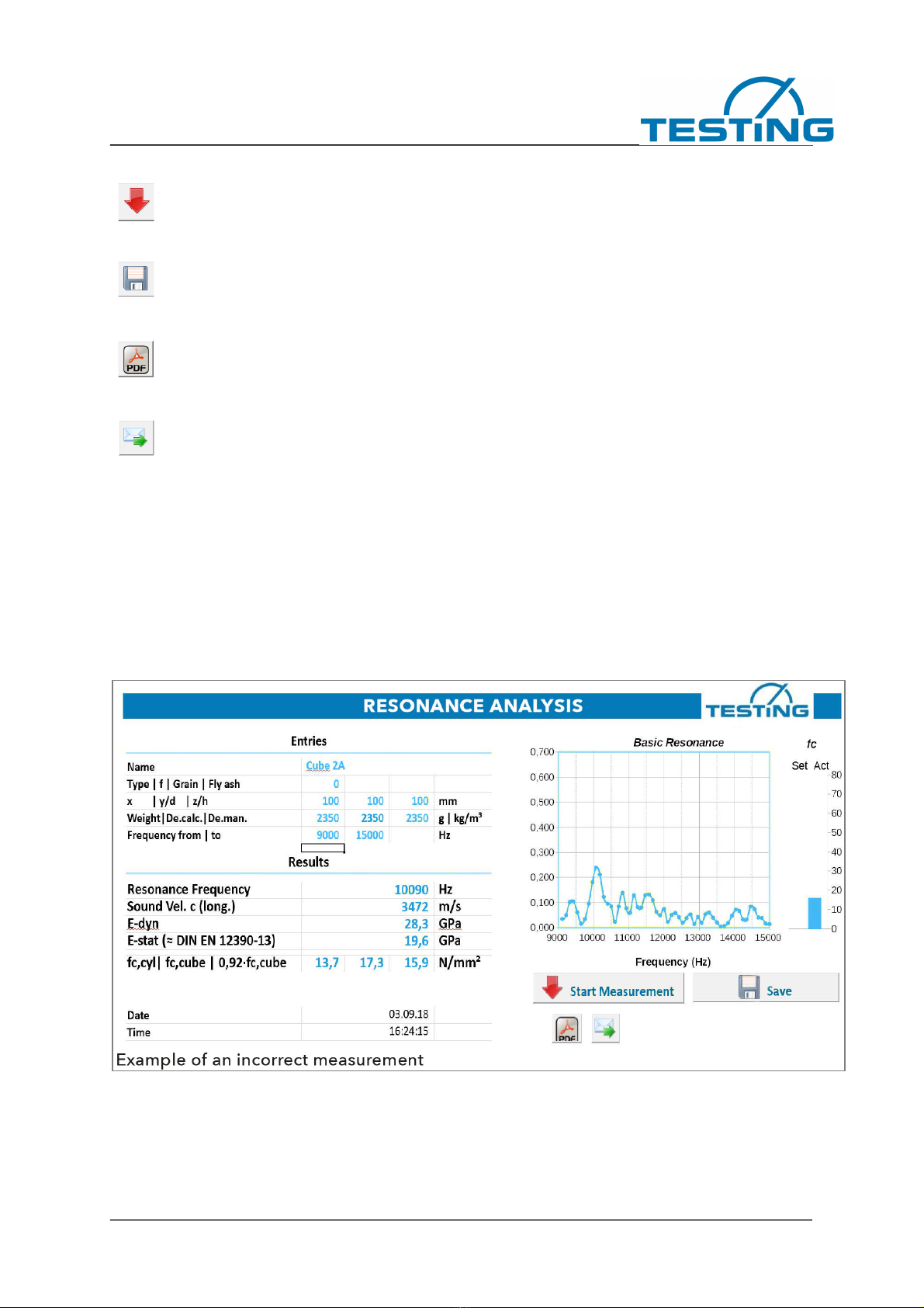
Resonant Frequency
This is the actual and most important measured value.
In the set frequency range, the signal frequency response recorded by the microphone is deter-
mined in the manner of a digital short-term Fourier transformation and also displayed graphically.
A resonance curve expected in the set frequency range is visible and evaluated with regard to its
maximum position in the frequency range and the resonance frequency is used to determine the
corresponding elastic material constants.
Velocity of sound
The pure material constant sound velocity is determined from the resonant frequency and sam-
ple dimensions.
Solids have different types of sound wave propagation, each with its own speed. In an isotropic
solid such as concrete (uniform behaviour in all directions) there are two types of waves in the
unlimited medium, which propagate at different speeds and are described by two independent
elastic constants. These waves are generally detected by ultrasound, since the larger dimen-
sions of the specimens do not play a role in the small wavelengths and the transit time measure-
ments.
In resonance measurements, the interfaces with their abrupt elastic property changes come into
play and complicate sound propagation, according to the sample dimensions. Sound propagation
is simplest measured in long bars where the transverse dimensions are small compared to the
wavelengths. For the velocity of sound determined by longitudinal oscillation resonance the
following applies:
c-shaft = radical (E/den)
and therefore: E = den*c2 (E = Young's modulus and den = density)
In this table result cell, c always means shaft speed. Other measured velocities, including
torsional wave velocities, are converted by means of relationships between elastic constants and
consideration of the specimen shape.
If the transverse contraction coefficient must be used, the mean value 0.2 valid for concrete is
used. The possibility of variation of 0.14...0.26 for concrete has little effect on the result.
Due to the cube specimen shape, which is widely used in the concrete industry, not a longitudi-
nal oscillation shape but the isolated lowest torsional oscillation was selected for reliable detec-
tion, which is converted into a comparable longitudinal speed of sound. The cube basic frequen-
cies are described in:
Harold H. Demarest, Jr. The journal of the Acoustical Society of America Volume 49 Number3
(Part 2) 1971, Cube-Resonance Method to Determine the Elastic Constants of Solids
E-dyn
The dynamic modulus of elasticity is a pure material property, not dependent on specimen geom-
etry and measuring conditions. For concretes, it is largely identical to the modulus of origin of the
stress-strain curve.