Telect GMT Series Manuel utilisateur

© Telect, Inc., All Rights Reserved, 130339-7 A0
1.509.926.6000 :: telect.com
High-Power 20A GMT Series Fuse Panels
Power :: 20HPGMTXX
User Manual
Applys to : 20HPGMT05R :: 20HPGMT05FR :: 20HPGMT05BNR :: 20HPGMT05BNR-24 :: 20HPGMT12R-75 ::
20HPGMT03R :: 20HPGMT02R

© Telect, Inc., All Rights Reserved, 130339-7 A0
1.509.926.6000 :: telect.com
ii
High-Power 20A GMT Series Fuse Panels
Power :: Models 20HPGMT
Table of Contents
1.1 Overview ................................................................................................................................1
1.1.1 Specications ..............................................................................................................2
1.1.2 Standard & Special Features ......................................................................................5
1.1.2.1 Bay & Failure Alarm Options ...............................................................................6
1.1.2.2 Fail-Safe Circuit ...................................................................................................7
1.1.2.3 Power-Line Noise Filter .......................................................................................7
1.2 Installation ..............................................................................................................................8
1.2.1 Rack-Mounting Conditions and Considerations ..........................................................8
1.2.2 Inspection ....................................................................................................................8
1.2.3 Installing the Panel .................................................................................................9
1.2.4 Replacing the Alarm Board ....................................................................................13
1.3 Service ................................................................................................................................. 13
1.3.1 Owner Maintenance ...................................................................................................13
1.3.2 In-Warranty Service ....................................................................................................14
1.3.3 Out-Of-Warranty Service ............................................................................................14
1.3.4 Repacking for Shipment .............................................................................................14
1.4 Parts & Accessories.............................................................................................................. 14
1.5 Diagrams .............................................................................................................................. 16
1.5.1 Block Diagram.............................................................................................................16
1.5.2 1RU Dimensions ........................................................................................................17
1.5.3 2RU Dimensions ........................................................................................................18
1.6 Certicate of Conformity ...................................................................................................... 19
List of Figures
Figure 1 - 20HPGMT05BNR (1RU Panel) Front and Rear View ................................................1
Figure 2 - 20HPGMT12R-75 (2RU Panel) ..................................................................................1
Figure 3 - Model 20HPGMT05R (Front View) .............................................................................2
Figure 4 - Alarm Panel .................................................................................................................5
Figure 5 - Model 20HPGMT05BNR (Rear View) .........................................................................6
Figure 6 - Standard Alarm Hookups ............................................................................................6
Figure 7 - Alarm Hookups ............................................................................................................7
Figure 8 - Mounting Dimensions ..................................................................................................9
Figure 9 - Ground Lug Connection ............................................................................................ 10
Figure 10 - Compression Lug Inputs ..........................................................................................10
Figure 11 - Replacing the Alarm Board ...................................................................................... 13
Figure 12 - Power, Battery Return and Fuse Circuit .................................................................. 16

© Telect, Inc., All Rights Reserved, 130339-7 A0
1.509.926.6000 :: telect.com 1
High-Power 20A GMT Series Fuse Panels
Power :: Models 20HPGMT
1.1 Overview
Telect’s High-Power 100A GMT Series Fuse Panels
provide protected secondary distribution of -48
VDC power to telecommunications equipment at
the bay level (20HPGMT05BNR-24 is 24VDC).
Fuse panels are available for GMT outputs up to
20A per position in dual-circuit (10/10, 15/15, and
20/20) panel congurations.
Standard features include
• Dual-circuit, 100A input buses, -48
VDC (20HPGMT05BNR-24 is 24VDC)
• Discrete GMT fuse positions: 20A capacity w/o fuse
management for heat dissipation
• Alarm circuit board replaceable with panel in
service (hot-swap)
• Minimal rack space: one, 1.75”.
• EIA or 2”. WECO rack unit (1RU)
• for rear access connections; 2RU for
• total front access of dual-circuit 10/10 conguration
• 19”. or 23”. rack mounting, with mounting brackets
provided. Dual-Circuit 20/20 Panel
(20HPGMT02R) requires a 23-in. rack.
• Transparent terminal cover meets electrical and
equipment safety standards.
• Dummy GMT fuses are provided for all fuse
holders.
• Holes provided in chassis for inserting colored fuse
designation pins
• All 20HPGMT panels are NEBS (Level 3) and CE
certied.
• Fire rating: UL 94V-0 and/or VW-1 (for wiring)
• All models except 20HPGMT05R are recognized
by UL for USA and Canada. 20HPGMT05R is UL
listed for USA and Canada.
Figure 1 - 20HPGMT05BNR (1RU Panel)
Front and Rear View
Figure 2 - 20HPGMT12R-75 (2RU Panel)

© Telect, Inc., All Rights Reserved, 130339-7 A0
1.509.926.6000 :: telect.com
2
High-Power 20A GMT Series Fuse Panels
Power :: Models 20HPGMT
Special features include
• Bay Alarm Circuitry (20HPGMT05BNR and 20HPGMT05BNR-24)
• Fail-Safe Circuitry (20HPGMT05FR only): load sharing permits either feed to power all loads if the other
feed fails.
• Noise Filter Circuitry (20HPGMT05BNR and 20HPGMT05BNR-24)
Telect’s High-Power GMT Series Fuse Panels use discrete, not modular, GMT fuse holders, to limit heat buildup
when using 15A and 20A GMT fuses.
Figure 3 - Model 20HPGMT05R (Front View)
1.1.1 Specications
Environment: Specications:
Temperature range -5°C to 55°C (-23°F to 131°F)
Humidity 5% to 85% and noncondensing
Altitude range -197 ft to 13,100 ft (-60 m to 4000 m)
Acoustic noise 0 dBA above ambient
Fit & Finish Specications:
Material
(Custom color/nish available)
Cold-rolled steel, powder-coat telephone grey, baked
polyure- thane. Clear polycarbonate protective
terminal cover.
Weights (Approximate) Specications:
Weight 8 to 12 lb (~3.5 to 5.5 kg), depending on model
POWER
© Telect, Inc., All Rights Reserved, 130339-7 A0
1.509.926.6000 :: telect.com 3
High-Power 20A GMT Series Fuse Panels
Power :: Models 20HPGMT
Mechanical Interface: Specications:
Input terminals — Compression Stud: 1⁄4-20 with nut. (Use 7/16-in. [12 mm] socket.)
Lugs: Dual-hole compression lug (5/8 i n . c e n t e r t o c e n t e r ) .
0.516 in. (13.4 mm), max. lug width
Cable: Up to 1/0 AWG copper, depending on input
interruption device
Torque: 62 in.-lb (~6.8 N•m), max.
Output terminals —
Wire binding / Compression
Screw: #6 Phillips* panhead
Wire: 14 to 22 AWG, copper wire Lug: 10 to 22 AWG,
copper wire
Spacing: 3/8 in. (9.5 mm) centerline with barrier distance of
0.260 in. (6.6 mm)
Torque: 9 in.-lb (~1.0 N•m), max.
Alarm terminals — Wire Wrap 0.045 in. square wirewrap pins on 0.156 in. centers. Use 18 to
22 AWG copper
Ground terminals Screws: 2, #10 Phillips* panhead
Lugs: Single- or dual-hole compression lug (5/8in.
center to center). Dual-hole lug is recommended.
Cable: Up to #6 AWG copper for single-hole lug (Conductor
size depends on input interruption device.)
Torque: 21 in.-lb (~2.5 N•m), max.
* Screws with cross-recessed heads
Dimensions: Specications:
Dimensions (nominal) without brackets for all but
20HPGMT12R-75 & 20HPGMT02R
Width: 17 in. (432 mm)
Height: 1.75 in. (44.4 mm)
Depth: 12 in. (305 mm)
Dimensions (nominal)
without brackets for 20HPGMT02R
Width: 21 in. (533 mm)
Height: 1.75 in. (44.4 mm)
Depth: 12 in. (305 mm)
Dimensions (nominal) without brackets for 20HPG-
MT12R-75
Width: 17 in. (432 mm)
Height: 3.5 in. (89 mm)
Depth: 7.5 in. (190 mm)
† See Pages 17 and 18 for exact dimensions.

© Telect, Inc., All Rights Reserved, 130339-7 A0
1.509.926.6000 :: telect.com
4
High-Power 20A GMT Series Fuse Panels
Power :: Models 20HPGMT
Electrical Interface: Specications:
Operating voltage -48 Vdc, both sides
Current capacity
All Except 20HPGMT05FR
20HPGMT05BNR
20HPGMT05BNR-24
20HPGMT05FR
20HPGMT05BNR
20HPGMT05BNR-24
100A per bus (200A total for dual-circuit panels), max.
75A per bus (150A total for both buses)
Fuse capacity: 20, 30, or 40 (total, both circuits)
Maximum input interruption device rating • 125A for all models except those with noise lters.
• 90A for models with noise lters (20HPGMT05NR &
20HPGMT05BNR-24)
Maximum output interruption device rating 20A GMT fuse
Interrupt rating 450A
Short circuit withstand current 450A
Alarm contact relay 2A
Alarm board power rating @ 48 Vdc 1W
Panel heat dissipation per 100A bus @% load 1.0W (3.4 Btu/hr) @ 0%
1.2W (4.1 Btu/hr) @ 25%
4.8W (16.5 Btu/hr) @ 50%
11.4W (38.7 Btu/hr) @ 75%
21.3W (72.6 Btu/hr) @ 100%
Percentage of full load heat dissipa- tion at nominal
voltage
less than 1% of total load wattage

© Telect, Inc., All Rights Reserved, 130339-7 A0
1.509.926.6000 :: telect.com 5
High-Power 20A GMT Series Fuse Panels
Power :: Models 20HPGMT
1.1.2 Standard & Special Features
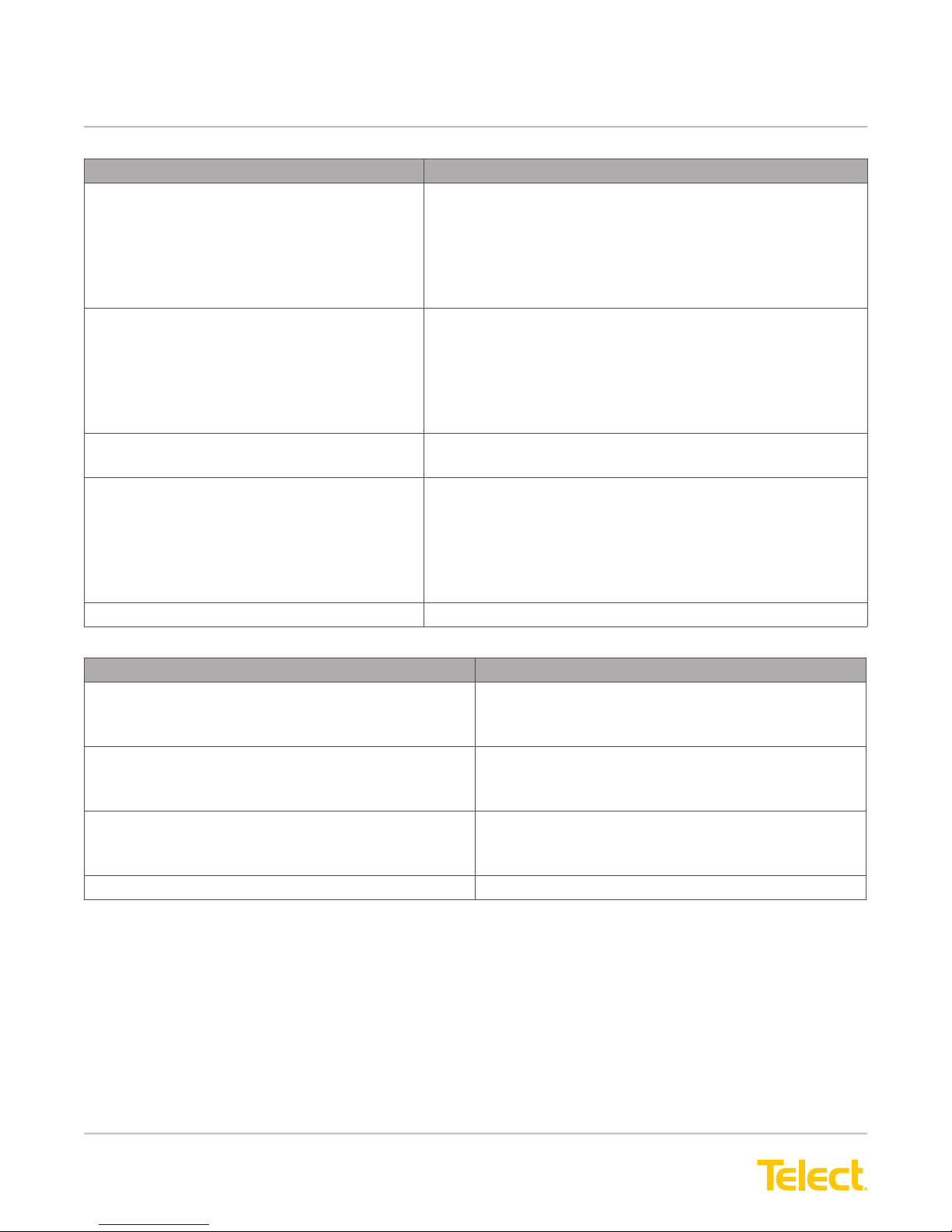
The following table compares the features of all standard 20HPGMT panels. All panels include a rear or front
transparent cover and most, except as footnoted in the following chart, can be mounted in either 19”. or
23”. racks. The paragraphs that follow briey describe some of the standard and special features included
with these panels.
Table 1 - Product Comparison Chart
Model No. Fuse Array -48 Vdc -24 Vdc Bay Alarm Fail-Safe
Circuit
Noise
Filter
20HPGMT05R X
20HPGMT05FR X X
20HPGMT05BNR X X X
20HPGMT05BNR-24 Dual 10/10 X X X
20HPGMT12R-75 (Front
Access - 2RU)
X
20HPGMT03R Dual 15/15 X
20HPGMT02R (23 inch
only)
Dual 20/20 X
GMT fuses are available in capacities ranging from 0.18A to 20A. A unique feature of the Telect High-Power GMT
Fuse Panel is that the fuse positions are oriented so the identication ags face down to provide easy location
of a blown fuse when the panel is at the top position of a relay rack or bay. (GMT splash covers are optional for
maximum safety when fuses blow.) Another unique feature of the GMT panels is a small hole below each fuse
position to accommodate color-coded optional designation pins. Designation pins are useful for quickly identifying
required fuse positions and rating of the fuses. The panel is delivered with dummy fuses in all positions.
The standard front panel includes dual-color LEDs for power and failure alarms on the face of an easily
removable/replaceable alarm card:
• The POWER LEDs are green when power is on
and red when power to that side goes off.
• The FAIL ALARM LED is green when all installed
fuses are OK and red when any installed, operable
fuse blows.
A POWER B POWER
FAIL
ALARM
OHPGMT05R
SN: 0206381 L#:E179636
WK-YR: 11-1999
Rev: A
20A MAX/FUSE
U
LUS LISTED
C
Figure 4 - Alarm Panel
Below the LEDs and alarm card is a pull-out circuit
designation card accommodating up to 40 circuit des-
ignation entries.

© Telect, Inc., All Rights Reserved, 130339-7 A0
1.509.926.6000 :: telect.com
6
High-Power 20A GMT Series Fuse Panels
Power :: Models 20HPGMT
The back panel of the 1RU panels contains input and output terminal connections (NEG or POS connections at
the top; RTN connections below), chassis ground connections, and wirewrap pins for external alarm hookups.
Figure 5 - Model 20HPGMT05BNR (Rear View)
1.1.2.1 Bay & Failure Alarm Options
The panel is available with alarm relays for standard remote/visual/audible failure alarms to light lights and
sound alarms when either power feed to the panel fails and/or any fuse blows. Along with the standard alarms,
Models 20HPGMT05BNR and 20HPGMT05BNR-24 include major/ minor bay alarms. Bay alarms are controlled
externally to turn on the panel’s Form C relay contacts in-circuit with external bay devices or connections.
Whenever a bay alarm occurs, the A POWER LED (for a major alarm) or B POWER LED (for a minor alarm) will
blink until external control is turned off.
Model 20HPGMT05FR includes enhanced power/fuse failure
alarms thatreplace the standard failure alarms. Where the
standard failure alarm doesn’t differentiate between power
or fuse failure, the enhanced power/fuse failure alarms
differentiate between A POWER, B POWER,and fuse failures
NC
C
NO
NC
C
NO
R
TNRT
N
R
E
M
O
T
E
V
I
S
U
A
L
A
U
D
I
B
L
E
Externa
l
Alarm
Device
E
xternal
Al
arm
D
evice
Figure 6 - Standard Alarm Hookups

© Telect, Inc., All Rights Reserved, 130339-7 A0
1.509.926.6000 :: telect.com 7
High-Power 20A GMT Series Fuse Panels
Power :: Models 20HPGMT
-Vdc-Vdc
Maj In Maj RTN Min In
Min RTN
Maj NC
Maj NO C
Min NC
Min NO
External
Alarm
Device
External
Alarm
Device
NC
C
NO
NC
C
NO
-Vdc RTN
-Vdc
RTN
A
PWR
B
MAJ MIN PWR
A
PWR
B FUSE
NC
C
NO
A
R
PWR
FUSE
NC
C
NO
External
Alarm
Device
External
Alarm
Device
Bay Alarms (20HPGMT05BNR
& 20HPGMT05BNR-24)
Enhanced Alarms (20HPGMT05FR)
Figure 7 - Alarm Hookups
1.1.2.2 Fail-Safe Circuit
Schottky diodes are cross-connected at the input to the power distribution circuits. When both power supplies are
energized in a dual-circuit panel, power is balanced between the two supplies by the diodes. If one power supply
loses its power or is shut down, the other supply shares its power with both outputs (A and B) through the
Schottky diodes. The battery return circuits for A and B are common since both circuits must operate from either
the A or B power source.
The fail-safe feature reduces the A and B inputs to 75A maximum for each bus (total 150A per panel). The
fail-safe feature also includes the enhanced failure alarms described previously.
NOTE: For the fail safe load sharing to function properly, the capacity of each of the user-supplied external feeder
fuses or breakers must be greater than the total load of the panel’s A and B outputs combined. For
example, if the panel’s total Load A = 10A and Load B = 10A, then the feeder fuse for Side A and Side B must
each be at least 20A (up to 125A). If the panel goes into Fail Safe mode, the lone input terminal can handle up
to 150A.
1.1.2.3 Power-Line Noise Filter
The lter characteristics under load are such that high-frequency transients are suppressed below effective
interference levels for telecommunications equipment used with the panel. With this lter option, the max capacity
of the bus is 75A. Typical lter characteristics are:
60 Hz -44dB 200 Hz -58dB 1kHz -96dB 10kHZ -102dB

© Telect, Inc., All Rights Reserved, 130339-7 A0
1.509.926.6000 :: telect.com
8
High-Power 20A GMT Series Fuse Panels
Power :: Models 20HPGMT
1.2 Installation
1.2.1 Rack-Mounting Conditions and Considerations
Elevated operating temperature: If you install this equipment in a closed or multi-unit rack assembly, the
operating ambient temperature of that environment may become higher than room temperature. Be sure to install
the equipment in an environment that can become no warmer than the manufacturer’s specied maximum
ambient temperature (Tma).
Reduced air ow: Make sure the air ow around the equipment in a rack is enough for safe operation of the
equipment.
Mechanical loading: To prevent an accident, make sure the equipment load is even.
Circuit overloading: To prevent problems with the over-current protection and supply wiring,
take care not to overload the circuits. Pay attention to equipment nameplate ratings.
Reliable earthing: Maintain reliable earthing of rack-mounted equipment. Pay attention to supply connections as
well as direct connections to the branch circuit (i.e., use of power strips).
Disconnect device: Incorporate an easy-to-reach disconnect device in the building’s installation wiring.
1.2.2 Inspection
Please read and understand all instructions before beginning installation. If you have questions, contact Telect
Technical Support at [email protected] or call 1.509.926.6000.
When you receive the equipment, carefully unpack it and compare it to the packaging list. Please report any
defective or missing parts to Telect Quality at [email protected] or call 1.509.926.6000.
Telect is not liable for transit damaged. If the product is damaged, please report it to the carrier and contact Telect
Quality.
Autres manuels pour GMT Series
1
Ce manuel convient aux modèles suivants
8
Table des matières
Autres manuels Telect Unité de distribution d'énergie


