tekton 46875 Manuel utilisateur

WARNING: BEFORE USE, READ AND UNDERSTAND OPERATOR'S MANUAL. Wear impact-resistant protective
eyewear in work area at all times. This reel must only be mounted to a load bearing structural object such as a
stud, rafter, or floor which can support the combined weight of reel and hose and can withstand pulling forces on
hose when in use. Air hose is designed for use on regulated air compressor systems delivering less than 250 PSI.
DO NOT EXCEED 250 PSI. Be sure to restrain hose as it rewinds—do not allow hose to rewind at full speed.
Never exceed air pressure rating for any air tool. Read and follow all guidelines specified in the air tool owner’s
manual. Certain air tools, such as paint spray guns, sanders, grinders, and sandblasting equipment, present
specific dangers and hazards. Consult applicable material safety data sheet for precautions and possible respirator
recommendation.
OPERATOR’S MANUAL
STORE THIS MANUAL IN A SAFE
PLACE FOR FUTURE REFERENCE
®
AUTO REWIND AIR HOSE REEL
Items
46875, 46878
Save time, contact us first.
888-648-3371
NEED HELP?
!
?

Bend Restrictor
Hose Stopper
Model # 46875
• Air Hose Size: 3/8" x 50'
•Reel Air Inlet (F): 1/4" NPT
•Air Hose Outlet (M): 1/4" NPT
•Max Working Pressure: 250 PSI
•Max Burst Pressure: 1100 PSI
•Maximum Air Flow: 25 CFM
Model # 46878
• Air Hose Size: 1/2" x 50'
•Reel Air Inlet (F): 1/2" NPT
•Air Hose Outlet (M): 1/2" NPT
•Max Working Pressure: 250 PSI
•Max Burst Pressure: 1200 PSI
•Maximum Air Flow: 35 CFM
Guide Arm
Guide Arm
Air Inlet
Roller Guide
Drum
Locking Pawl
Support Leg
Support Leg
Base
For complete parts diagram, see
page 6-7, centerfold of book
page 2

Locking pawl
Locking gear
PULL
1
R
O
T
A
T
E
page 3
OPERATING AIR HOSE REEL
BEFORE MOUNTING AIR HOSE REEL, please take a few minutes to understand how it works. Practice operating it a
few times, pulling hose out and rewinding it back onto the drum. This will familiarize you with basic functions and can help
you understand where best to mount the air hose reel.
This air hose reel automatically rewinds air hose using an internal recoil spring. When hose is pulled from reel, it is pulled against
the tension of the recoil spring. The more hose is pulled out, the greater the tension built up in the recoil spring. NEVER LET GO
OF HOSE WHILE PULLING FROM REEL. Letting go will allow hose to rewind at uncontrolled speed, possibly damaging the
internal spring or roller guides.
1. Grasp air hose and pull slowly from reel. As hose is pulled from reel, the entire reel drum rotates. To prevent extra wear on air
hose, periodically check to be sure roller guides inside collar are rolling smoothly.
2. As reel drum rotates, the locking gear and pawl make a short series of six clicking sounds each 1/2 revolution. In one
revolution, there are a total of twelve locking positions.
3. TO LOCK REEL IN POSITION, slow down pulling motion as desired length of hose is reached. While pulling slowly, listen
for each short series of clicking sounds. As the pawl is clicking, stop pulling hose and decrease tension. The drum should lock
in position.
TO REWIND HOSE ONTO REEL, slowly pull hose out until the first series of clicks stops. This means the locking pawl has
cleared the locking gear. DO NOT LET GO OF HOSE! Slowly allow hose to rewind onto drum until hose stopper rests against
guide collar.
2
3

FLOOR
CEILING
WALL
page 4
MOUNTING HOSE REEL
Choosing a Location
DO NOT MOUNT HOSE REEL OUTDOORS OR ON VEHICLE. This hose reel is not designed to resist constant
exposure to weather or continuous vibration. Mount under cover in an area not directly exposed to weather.
Reel can be mounted on the floor, ceiling, or wall, wherever it is convenient. When choosing a location, remember that the
must be mounted reel to a load-bearing structural member capable of supporting combined weight of reel, hose, and
forces caused by pulling or maneuvering hose. Mounting reel near air compressor may be desirable since you can connect
the two with a shorter, less expensive length of hose. Also, air compressor controls will be conveniently nearby.
COMPRESSOR
WHIP HOSE
LEAD-IN HOSE LEAD-IN HOSE
TOOL
SHUT-OFF VALVE
RIGID PIPE
REGULATOR
MOISTURE TRAP
LUBRICATOR
AIR
HOSE
REEL
TYPICAL COMPRESSED AIR SYSTEM

page 5
TYPICAL INSTALLATION
WALL STUDS
MOUNTING PLATE
Example: 2x10 lumber
Lag bolt, lock washer,
and flat washer
4X 4X 4X
Machine bolt, two flat
washers, lock washer,
and nut
Machine bolt, lock washer,
flat washer, and anchor
TYPICAL FASTENERS AND HARDWARE COMBINATIONS
WOOD METAL MASONRY
INSTALLATION
Use included mounting
template to mark and drill the
hole locations.
MOUNTING TEMPLATE
Temporarily install the upper
fasteners leaving a 1/4" gap to
accommodate thickness of base.
1/4"
GAP
1. 2.
3. 4.
Guide base plate key holes over
the preinstalled fasteners.
Keep hose reel supported
at all times until all fasteners
are tight.
Install the lower fasteners
and tighten.
Remove the upper fasteners, and
reinstall with appropriate washers
and tighten all fasteners.
Keep hose reel supported
at all times until all fasteners
are tight.
KEYHOLE
SLOTS

1
2
6
5
4
12
5
14
13
10
7
910
8
11
11
3
30
99011
99016
page 6
44
42
39
40
43
41
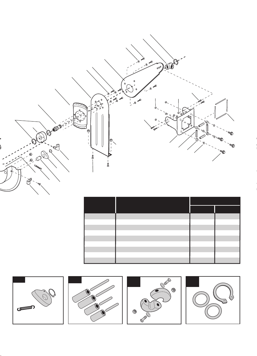
PARTS LIST
1. Recoil Spring Cover
2. Recoil Spring
3. Recoil Spring Hub
4. Spring Cover Bolt
5. Nut (8)
6. Drum
7. Guide Arms (2)
8. Support Legs (2)
9. Base
10. Bolt (16)
11. Washer (16)
12. Nut (4)
13. Bolt (4)
14. Nut (4)
15. Guide Collar
16. Rollers (4)
17. Roller Pins (4)
18. Bolt (4)
19. Washer (4)
20. Rubber Bushing (4)
21. Nut (4)
22. Bolt (4)
23. Nut (4)
24. Air Inlet Axle
25. Air Inlet
26. Retaining Ring (2)
27. Retaining Ring
28. Air Outlet (To Hose)
29. Main Axle Bearing
30. Bolt
31. Locking Pawl
32. Tension Spring
33. Locking Pawl Axle
34. Retaining Ring
35. Locking Gear
36. Hose Clamp
37. Bolt
38. Nut
39. Hose Stopper
40. Bolt (2)
41. Washer (2)
42. Nut (2)
43. Air Hose
44. Bend Restrictor
35
10
25
8
7
32
21
15
20
26
29
24
31
36 37
38
27
22
19
18
16
14
28
46
23
13
47
11
33
34
22
17
ASSEMBLY DESCRIPTION 46845 46848
99011 3/8" Air Inlet Assembly •
99012 Locking Pawl Assembly •
•
99013 Guide Rollers and Pins •
•
99014 3/8" Hose Stopper Assembly •
99015 Main Spring •
•
99016 1/2" Air Inlet Assembly •
99017 1/2" Hose Stopper Assembly •
99043 3/8" O-Ring Kit •
99044 1/2" O-Ring Kit •
FITS THIS HOSE REEL
99012 99014
99017
99013 99043
99044
page 7

MAKING ADJUSTMENTS
Remove position bolts and nuts. Leave pivot
bolt in place. Adjust to one of three desired
positions. Reinstall fasteners and tighten.
1
2
3
12 3
page 8
Pivot Bolt
Position Bolt
Guide Collar
Air Hose
Adjusting the Guide Collar
Adjusting the Guide Arm
1 2
1. Pull out 3-4 feet of hose and secure the hose
reel drum.
Locking gear will disengage when bolts
are removed! Secure drum before
removing bolts.
2. Remove the bolts connecting the guide arms
to the support legs.
Locking gear will disengage when bolts
are removed! Secure drum before
removing bolts.
3. Rotate guide arm to one of two positions.
Replace bolts and tighten.
1
2
3
4
Reinstall bolts
as shown.
TWO PEOPLE ARE RECOMMENDED FOR THIS PROCESS. During the course of this adjustment, the locking gear
will disengage and become ineffective. Ask a second person to hold the drum to prevent it from spinning while
removing and reinstalling the guide arm bolts.
Adjusting Hose Stopper Position
The hose stopper determines the length of hose that remains outside of reel. To adjust stopper position:
1. First pull hose out past the desired position of hose stopper. Lock drum in position.
2. Loosen (but do not remove) both stopper bolts just enough so stopper can slide along hose.
3. Move stopper to desired position. Tighten stopper bolts until hose stopper cannot slide. Do not overtighten bolts.
Desired length
of hose
Loosen but do not
remove bolts

page 9
3. Unwrap one revolution of hose from
the reel.
4. Push the air hose through the roller
guide and reinstall hose stopper.
Keep drum locked at all times.
1. Pull out 2 feet of air hose and lock
drum. Remove air hose stopper.
2. Pull air hose back through the
roller guide.
Keep drum locked at all times.
3. Wrap one revolution of hose onto
the reel.
4. Push the air hose through the roller
guide and reinstall hose stopper.
Keep drum locked at all times.
1. Pull out 8 feet of air hose and lock
drum. Remove air hose stopper.
2. Pull air hose back through the
roller guide.
Keep drum locked at all times.
Adjusting Recoil Tension
Hose reel is shipped with spring tension properly set. Be aware that spring tension is calibrated to rewind entire length of air
hose. If you are working with only a portion of total air hose length or if you feel hose rewinds too quickly or too slowly, you
can easily adjust the tension of the main recoil spring.
DO NOT SET TOO MUCH TENSION IN SPRING. Damage to spring could result.
Decreasing Recoil Tension
Increasing Recoil Tension
U
N
W
R
A
P
2 FT
8 FT
W
R
A
P
12
34
12
34

ATTACHING INCOMING AIR
For consistent leak-free performance, air inlet is made of solid brass. Brass is a soft metal and extra care should be taken to
avoid cross threading. For a tight, leak-free connection, follow all instructions carefully.
Option 1
Wrap incoming air hose end with thread sealing tape. Thread air hose end into air inlet, taking care not to cross thread.
Tighten connection with wrench. Do not over-tighten.
Option 2
Locate included swivel nut connector. Wrap threaded end with thread sealing tape. Thread into air inlet, taking care not to
cross thread. Tighten connection with wrench. Do not over-tighten. Next, wrap end of incoming air hose with thread sealing
tape. Thread air hose into swivel end of connector, by turning swivel collar. Tighten connection with wrench. Do not
over-tighten.
To ensure optimum performance, check all connections for leaks. With air system pressurized, brush each
connection with soapy water. Inspect closely. Air bubbles indicate leaking air. Tighten any leaking fittings.
OPTION 2
OPTION 1
Lead-in
Hose
Lead-in
Hose
Swivel Nut
Connector
page 10
Ce manuel convient aux modèles suivants
1
Table des matières
Autres manuels tekton Outils


