© 2008 W 161 - 12/08 2 of 12
Definitions
Caution
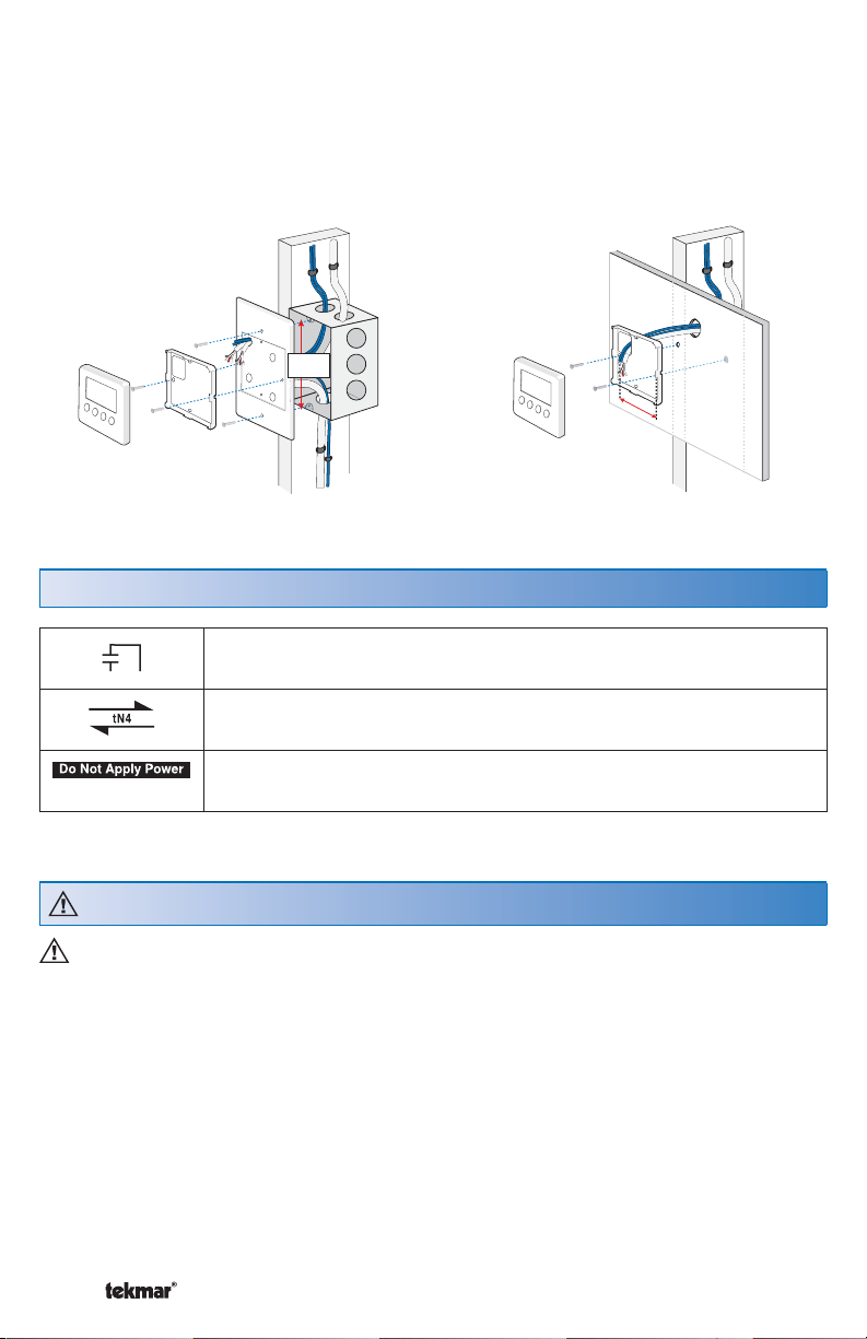
Rough-In Wiring
The following defined terms and symbols are used throughout this manual to bring
attention to the presence of hazards of various risk levels, or to important information
concerning the life of the product.
– Caution: Refer to accompanying documents.
– Caution: Refer to accompanying documents.
INSTALLATION
CATEGORY II – Local level appliances.
Improper installation and operation of this control could result in damage to the
equipment and possibly even personal injury or death. It is your responsibility to ensure
that this control is safely installed according to all applicable codes and standards.
This electronic control is not intended for use as a primary limit control. Other controls
that are intended and certified as safety limits must be placed into the control circuit.
Do not attempt to service the control. Refer to qualified personnel for servicing. There
are no user serviceable parts. Attempting to do so voids warranty and could result in
damage to the equipment and possibly even personal injury or death.
Choose the placement of the setpoint control early in the construction process to
enable proper wiring during rough-in.
Consider the following:
Interior Wall.
Keep dry. Avoid potential leakage onto the control. RH 80% to 88°F (31°C),
down to 50% from 104 to 122°F (40 to 50°C). Non-condensing environment.
No exposure to extreme temperatures beyond 32- 122°F (0 -50°C).
No draft, direct sun, or other cause for inaccurate temperature readings.
Away from equipment, appliances, or other sources of electrical interference.
Easy access for wiring, viewing, and adjusting the display screen.
Approximately 5 ft. (1.5 m) off the finished floor.
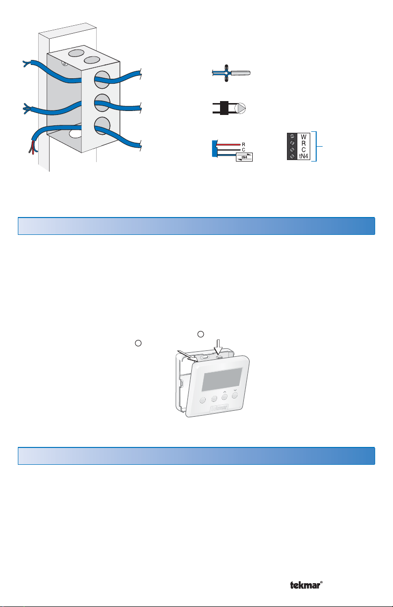
Use standard 18 AWG wire for the control power, relays, tN4 and sensor
connections.
Refer to the diagram below to determine the number of conductors to run from each
piece of equipment to the control location.