TeeJet Technologies MATRIX 430 Manuel utilisateur
MATRIX
®430
USER MANUAL
Entry level guidance
Software version 1.03

GETTING STARTED
1. Power on the console.
Setup machine
2. On guidance screen, press NAVIGATION AND GUIDANCE
OPTIONS tab to display options.
3. Press HOME button .
4. Press CONSOLE button .
►LCD Brightness
►Color scheme
►Units
►GNSS demo mode
►Screenshot
►Time zone
►Console information
5. Press HOME button .
6. Press CONFIGURATION button .
►Machine Conguration
►Lightbar spacing
►GNSS
Setup guidance
7. From the Home screen, press GUIDANCE button .
8. On guidance screen, press NAVIGATION AND GUIDANCE
OPTIONS tab to display options.
►Guidance mode – Straight AB guidance ,
Curved AB guidance , Circle pivot guidance , Last
pass guidance or no guidance
►Create AB guideline
A
B
►Create boundary
►Set return point
Start mapping
9. Press VEHICLE icon in the center of the guidance screen
to turn on or off application mapping.
Guidance screen includes
►Selectable information – Speed , total applied
area , application time or swath number
►Lighbar and Navigation Activity – GNSS status, cross track
error or current activity
►Status Bar – GNSS , guidance mode ,
boundary area and Application mapping status
►A+ nudge feature A
►Transport mode
►Zoom
Start new job
To start a new job, delete old job data.
1. From the Home screen, press DATA button .
2. Press RECYCLE button .
A
A
#2
#3
#4
#6
#8
#9

1
98-05332 R1 EN
Matrix®430
MATRIX430 CONSOLE
GNSS antenna connection
Power connection
Integrated RAM mount
(assembly required)
Power button
USB port
with rubber cover
Standard RAM bracket
(assembly required)
Bright touch screen
System components
Connect +12v at 15/30
Connect GND to 31
Power Cable
45-05867
DC:xx/xx
Console, Matrix 430
CG430-GLO
Kit, RAM Mount
w/ Suction Cup
Power Cable
45-05645
DC:xx/xx
Connect to
+12v Only
POWER CABLE
45-05775
DC: XXXX
CAUTION CONN. TO
+12VONLY
GPS Patch Antenna
RXA-30 Antenna
Power Cables
Power/Sense/Speed Cables
Direct to Battery 45-05775
Lighter Adapter 45-05645
US 45-05970
EU 45-05969
COBO Adapter 45-05867
Status On/Off
SENSE
+12v
GPS Speed
POWER IN
Power/Sense/
Speed
45-05970 xx/xx
Power/Sense/
Speed
45-05969 xx/xx
POWER IN
Work On-Off
GPS Speed
All changes are saved automatically.
The console needs to be cycled off and back on when changing or
attaching equipment to the Matrix 430 system.
Recommended antenna installation
The GNSS antenna should be mounted as far forward as possible on
top of the cab on a metal surface of at least 4”/10 cm square.
Power on
1. Press POWER button .
Power off
1. Press POWER button .
2. Select from:
►Accept – to continue shut down
►Cancel – to keep the console on.
WARNING! Wait 30 seconds before restarting the console after
powering off.

2
www.teejet.com
Matrix®430
ICON REFERENCE
Guidance
Selectable information
Speed
Total applied area
Application time
Swath number
Show nothing
A
B
Mark A , Mark B
A
A+ nudge feature
Transport Mode
Navigation and guidance options tab
Home
Guidance modes
Straight AB guidance
Curved AB guidance
Circle pivot guidance
Last pass guidance
No guidance
Application boundary
Start
Finish
Cancel
Delete
Return to point
Mark
Go to point
Cancel
Delete
Close options
Zoom in/out
Conguration
Machine settings
Number of implement sections
Section widths
In-line implement offset distance
Lateral implement offset distance
Lightbar spacing
GNSS receiver conguration
Job Data
Total applied area
Bounded area
Application time
Delete
ALL
Reports
Console
LCD brightness
User interface colour scheme
Units
Demonstration GNSS
GNSS
Demo
Screenshot
Time zone
About

3
98-05332 R1 EN
Matrix®430
KEYBOARD ENTRY SCREENS
To change a value:
1. Press CURRENT VALUE.
2. Use the numeric keypad to enter a new value.
3. Select from:
►Accept – to save the settings
►Cancel – to leave the keypad without saving
Figure 1: Example of keyboard
(m)
1 2 3
3.66
Clear
4 5 6 <--
7 8 9
0 . +/-
HOME
Guidance
Used to view a computer-generated image of the vehicle
position displayed in the application area. From this screen all
setup and navigation options can be accessed via the tab on
the right side of the screen.
Conguration
Used to setup the machine settings, lightbar and GNSS
receiver.
Job data
Used to view or delete job data and export reports.
Console
Used to setup LCD brightness, colour scheme, units,
screenshot and time zone; start demonstration GNSS; and
view console information.
Calculator
A

4
www.teejet.com
Matrix®430
GUIDANCE
The Guidance Screen creates a computer-generated image of the vehicle position displayed in the application area. From this
screen all setup and navigation options can be accessed via the tab on the right side of the screen.
Status bar
Guidance bar
Painted coverage area
Overlap coverage area
Navigation guidelines
Vehicle with real-time representation of
active boom sections
Navigation and guidance options tab
Navigation and guidance options tab
Home – used to access Home screen
Guidance Modes – select one of ve (5) guidance modes:
Straight AB guidance , Curved AB guidance , Circle pivot
guidance , Last pass guidance , No guidance
Application Boundary – create or delete a boundary
Return to Point – create, guide to or delete a point
Close menu – used to close the Navigation and guidance
options menu
Zoom In/Out – adjust the vehicle’s view or perspective to the
horizon from vehicle view to bird’s eye view
Guidelines
A
– establish an AB guideline or shift line to the
vehicle’s current location
Transport mode – when enabled, all operation functions are
locked off and cannot be activated.
A
On screen guidance
• Guidelines:
◄Orange – active guidance line
◄Brown (multiple) – adjacent guidance lines
◄Black – boundary line
• Points – markers for established points:
◄Red point – Return to point
◄Blue point – Mark A
◄Green point – Mark B
• Coverage area – illustrates applied area and overlap:
◄Blue – one application
◄Red – two or more applications
• Zoom in/out & perspective – adjusts the vehicle’s view or
perspective to the horizon from vehicle view to bird’s eye view.
• Boom Sections:
◄Empty box – inactive boom
◄White box – active boom
Status bar
The status bar provides information on GNSS status, guidance
mode, boundary area, and implement control status.
GNSS status
Guidance mode
Bounded area status
Application mapping status

5
98-05332 R1 EN
Matrix®430
GNSS status
Red = no GNSS
GPS only
Green = DGPS,WAAS/RTK, GLONASS
Guidance mode
Straight AB guidance
Curved AB guidance
Circle pivot guidance
Last pass guidance
No icon = no guidance
Bounded area status
Outside boundary = currently traveling outside bounded area
Inside boundary = currently traveling inside bounded area
No icon = no boundary established
Application mapping status
Red = off
Green = on
Status/information screens
To display information:
1. Press status bar icon.
►GNSS status – displays information regarding number of
satellites in view, satellite quality and receiver ID
►Bounded area status – displays information regarding the
area in the current boundary
To remove the information box, tap the information box.
Guidance bar
The guidance bar keeps you informed of your choice of selectable
information (current speed, total applied area, application time, swath
number) and navigation activity (cross track error, current activity and
GNSS status).
Lightbar & Navigation Activity
Selectable Information Selectable Information
Lighbar & navigation activity
Lightbar spacing – used to represent the distance away from the
guideline or vehicle.
GNSS status – displays ashes “GPS” when GNSS is unavailable
Cross track error – displays the distance from your desired guideline
Current activity – displays activities such as mark an A or B point and
distance to return to a marked point
Selectable information
Speed – displays the current speed of travel
Total applied area – displays the total accumulated area that has
had application applied including double coverage areas
Application time – displays the total time application is active
during the current job
Swatch number – displays the current swath number in
reference to the initial guidance line. Number will be shown as a
positive number when the vehicle is to the right of the AB baseline or
a negative number when the vehicle is to the left of the AB baseline
1 2 3 4 5 6-6 -5 -4 -3 -2 -1
No information – shows no information in the display area

6
www.teejet.com
Matrix®430
Guidance Modes
To choose a Guidance Mode:
1. Press NAVIGATION AND GUIDANCE OPTIONS tab to
display navigation options.
2. Press GUIDANCE MODE button .
3. Select from:
►Straight AB guidance
►Curved AB guidance
►Circle pivot guidance
►Last pass guidance
►No guidance
NOTE: Offset to adjacent guidelines will be calculated using the
guidance width, which is encoded in Machine setup in
the Configuration options.
Straight AB guidance
Straight AB guidance provides straight line guidance based on A and
B reference points. The original A and B point are used to calculate
all other parallel guidelines.
No guidance
No guidance turns off guidance.
NOTE: No guidance mode does not delete established guide lines
or points from the console. To delete established/saved data
from the console, please refer to the Data management
section under Unit setup.
Last pass guidance
Last pass guidance offers true last pass navigation. The console will
automatically detect the nearest applied area and establish parallel
guideline based on that area.
NOTE: If a boundary is established but no application occurred
during the boundary process, guidance will not initiate.
Curved AB guidance
Curved AB guidance provides guidance along curved lines based on
an initial AB reference line. This initial baseline is used to calculate all
other guidelines.
NOTE: Curved guidance is recommended not to exceed 30° within
the AB guideline.
HINT: While working in a bounded area, the guidance pattern
extending beyond the established AB points will be straight
line guidance.
Circle pivot guidance
Circle pivot guidance provides guidance around a central location
that radiates inward or outward based on an initial AB reference line.
This initial baseline is used to calculate all other guidelines.
It is used for product application in a centre pivot eld while being
guided along a circular guideline that matches a centre pivot
irrigation system radius.
7
98-05332 R1 EN
Matrix®430
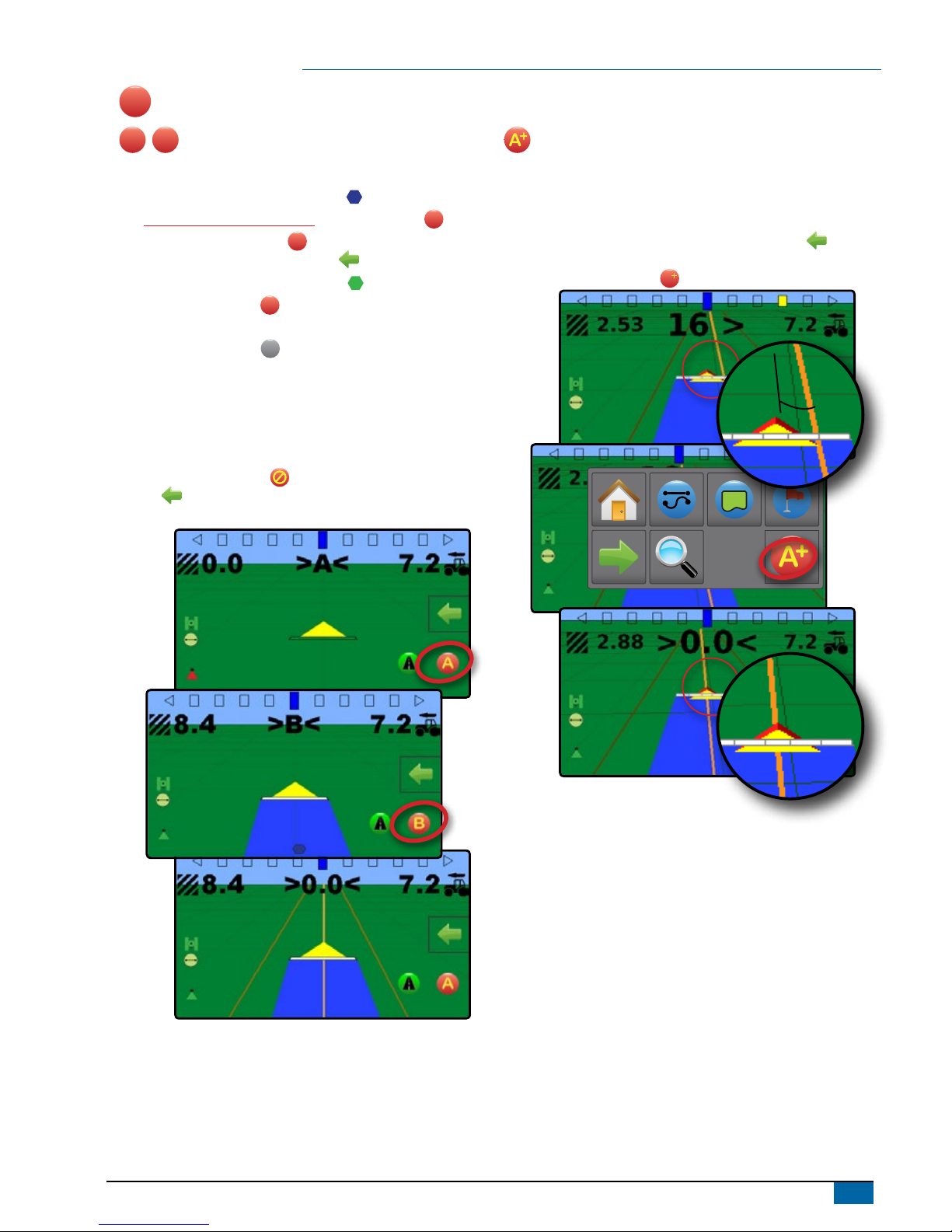
A
Guidelines
A
B
Marking A and B points
To establish an AB guideline:
1. Drive to the desired location of Point A .
2. While the vehicle is in motion, press MARK A icon
A
.
NOTE: a Mark A button
A
is also available on the
Navigation and guidance options menu
3. Drive to the desired location of Point B .
4. Press MARK B button
B
to establish the AB line.
The console will begin providing navigation information.
NOTE: The MARK B Icon Bis not available for selection (greyed
out) until the minimum distance is travelled (3.0 metres in
Straight or Curved guidance, 50.0 metres in Circle pivot
guidance).
It is not necessary to drive the entire circumference of the
centre pivot in order to initiate Circle pivot guidance.
Use CANCEL MARK button on the Navigation and guidance
options menu to cancel the Mark A command and revert to the
previous guideline (when established).
A
A+ nudge feature
The A+ nudge feature allows the current guideline to be shifted to the
vehicle’s current location.
To adjust the guideline:
1. Press NAVIGATION AND GUIDANCE OPTIONS tab to
display navigation options.
2. Press A+ NUDGE button A.
A

8
www.teejet.com
Matrix®430
Application Boundary
Application boundaries establish areas where application is
and is not to be applied. Boundaries can be established in all
guidance modes. One exterior boundary can be stored at a time.In
correspondence to your current location, the IN BOUNDARY icon
or OUT BOUNDARY icon is displayed on the status bar once
the boundary is established.
Creating a boundary
To establish an application boundary:
1. Drive to a desired location at the perimeter of the field/
application area.
2. Press NAVIGATION AND GUIDANCE OPTIONS tab to
display navigation options.
3. Press BOUNDARY button .
4. While the vehicle is in motion, press BOUNDARY button .
5. Travel the perimeter of the eld/area.
6. Finish boundary:
►Travel to within one swath width of the starting point. The
boundary will close automatically (the white boundary line will
turn black)
►Press BOUNDARY FINISH button . A straight line will
complete the boundary between your current location and the
starting point
NOTE: The BOUNDARY FINISH button is not available for
selection (greyed out) until the minimum distance is travelled
(five-times the swath width).
Use CANCEL BOUNDARY button under Boundary on
the Navigation and guidance options menu to cancel the new
eld boundary process and revert to the previous boundary (when
established).
Delete the boundary
To delete the established boundary:
1. Press NAVIGATION AND GUIDANCE OPTIONS tab to
display navigation options.
2. Press BOUNDARY button .
3. Press DELETE BOUNDARY button .
Autres manuels pour MATRIX 430
3
Table des matières
Autres manuels TeeJet Technologies GPS


