TechVision PEE1ENN2-W Manuel utilisateur

Table of Contents
1Product Overview ........................................................................................ 1
1.1 Intro to Product................................................................................................ 1
2Structure...................................................................................................... 2
2.1 Front Panel ..................................................................................................... 2
2.2 Rear Panel...................................................................................................... 3
3Networking Scene........................................................................................ 4
4Installation and Debug................................................................................. 5
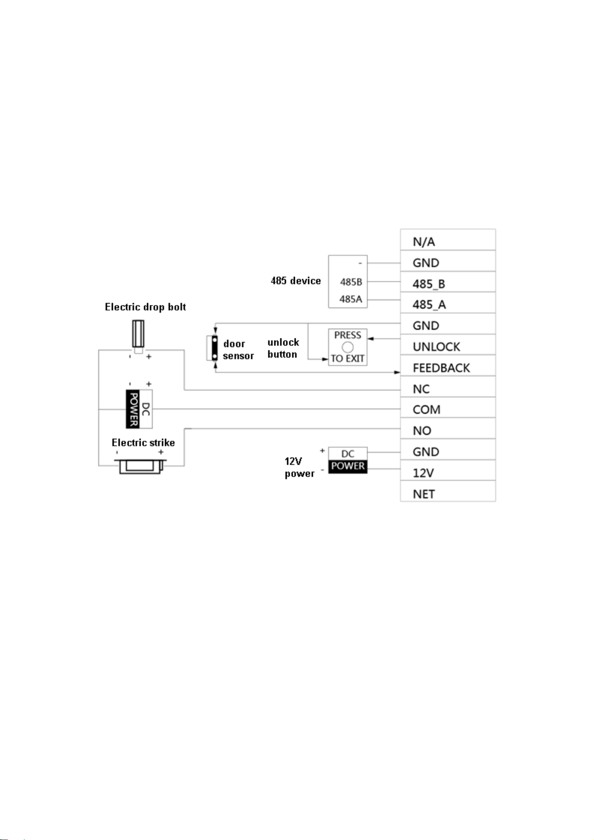
4.1 Device Wiring.................................................................................................. 5
4.2 Device Installation........................................................................................... 5
4.2.1 Screw.................................................................................................... 6
4.2.2 Installation Step .................................................................................... 6
4.3 Debug Device ................................................................................................. 7
4.3.1 Before Debugging................................................................................. 7
4.3.2 Debug Device ....................................................................................... 8
4.3.3 Successfully Debug............................................................................. 11
5Web Config.................................................................................................. 1
5.1 WEB Login and Logout ................................................................................... 1
5.1.1 Login..................................................................................................... 1
5.1.2 Logout................................................................................................... 1
5.2 System Config................................................................................................. 2
5.2.1 Local Config.......................................................................................... 2
5.2.2 LAN Config ........................................................................................... 7
5.2.3 Indoor Manager..................................................................................... 8
5.2.4 Network Config ................................................................................... 10
5.2.5 Video Set............................................................................................ 12
5.2.6 User Manager..................................................................................... 14

5.2.7 IPC...................................................................................................... 16
5.2.8 WIFI Info............................................................................................. 17
5.3 Info Search.................................................................................................... 17
5.3.1 Call History ......................................................................................... 18
5.3.2 Alarm Record...................................................................................... 18
5.3.3 Unlock Record .................................................................................... 18
5.4 Status Statistics............................................................................................. 19
6Basic Function Introduction........................................................................ 20
6.1 Monitor.......................................................................................................... 20
6.2 Call Function................................................................................................. 20
6.3 Unlock........................................................................................................... 20
6.4 Restore Backup............................................................................................. 20
Appendix 1 Technical Specifications....................................................................... 21

Important Safeguards and Warnings
Please read the following safeguards and warnings carefully before using the product in
order to avoid damages and losses.
Note:
Do not expose the device to lampblack, steam or dust. Otherwise it may cause
fire or electric shock.
Do not install the device at position exposed to sunlight or in high temperature.
Temperature rise in device may cause fire.
Do not expose the device to humid environment. Otherwise it may cause fire.
The device must be installed on solid and flat surface in order to guarantee
safety under load and earthquake. Otherwise, it may cause device to fall off or
turnover.
Do not place the device on carpet or quilt.
Do not block air vent of the device or ventilation around the device. Otherwise,
temperature in device will rise and may cause fire.
Do not place any object on the device.
Do not disassemble the device without professional instruction.
Warning:
Please use battery properly to avoid fire, explosion and other dangers.
Please replace used battery with battery of the same type.
Do not use power line other than the one specified. Please use it properly.
Otherwise, it may cause fire or electric shock.
Special Announcement
This manual is for reference only.
All the designs and software here are subject to change without prior written
notice.
owners.
If there is any uncertainty or controversy, please refer to the final explanation of
us.

1
1 Product Overview
1.1 Intro to Product
Digital villa VTO has easy operation, simple installation and support:
WIFI
Mobile phone live preview
Call VTH, and perform video talk
Door unlock by card
One-click MGT center
Vandal-proof alarm and etc.

2
2 Structure
2.1 Front Panel
Device front panel is in Figure 2-1. Description of each component is in Chart 2-1.
Figure 2-1
No.
Port Name
Note
1
MIC
Audio input.
2
Camera
It monitors corresponding door region.
3
Card Area
Authorize IC card to unlock (card issuing),
swipe card to unlock.
4
Indicator
In standby status, blue light is NO.
Network offline, blue light flashes when
call VTH or MGT center.
5
Call
Button
Call MGT center or VTH.
6
Speaker
Audio output.
Chart 2-1

3
2.2 Rear Panel
Device rear panel is in Figure 2-2. Description of each component is in Chart 2-2.
Figure 2-2
Chart 2-2
No.
Component Name
Note
1
Bracket Position
Bracket used to fix device and wall.
2
Vandal-proof
Switch
When villa VTO is forced to leave wall, it will alarm and
send alarm to MGT center.
3
Alarm
Input/output
Interface
1-ch alarm input.
4
RESET Key
Shortly press this key to config reset WIFI.
Long press this key for 10s, system will restore
default settings.
5
RJ45 Interface
Standard Ethernet cable, support POE power.
6
Power Input
Interface
DC 12V input, support 9V-26V wide voltage, with
anti-reverse connection.

5
4 Installation and Debug
4.1 Device Wiring
Device wiring is in Figure 4-1.
Figure 4-1
4.2 Device Installation
Warning:
Avoid installation in poor environment, such as condensation, high temperature, oil
stain, dust, corrosion or direct sunlight.
Project installation and debugging must be done by professionals. Please do not
open the device in case of failure, and please contact after sales service.

6
4.2.1 Screw
For installation, please use screw according to Chart 4-1.
Component Name
Illustration
Quantity
M4×30 cross pan head
machine screw
2
Chart 4-1
4.2.2Installation Step
VTH installation is in Figure 4-2.
Figure 4-2
Steps:
Step 1. According to position of bracket, dig hole on installation surface (such as wall).
Step 2. Insert expansion bolt in hole you just dug.
Step 3. Fix bracket on designated position with screw.
Step 4. Fix device on bracket with screw.
Step 5. Install tail sealing element at device tail. Use two M4×30 screw pan head
machine screw to fix bracket on 86 box.
Ce manuel convient aux modèles suivants
1
Table des matières


