MINI-CONNECTOR
PLUG-SOCKET IP66/IP68
(1) Wide range of accessories available for smaller cables or single conductors.
Techno s.r.l.
Via Bancora e Rimoldi, 27 | 22070 Guanzate (CO), Italia | Tel. +39 031 976445 | fax +39 031 976680
TH389U
CODES THB.389.AxxU / THB.389.BxxU / THB.389.AxxU.R
Number of poles 3 - 4 poles
Type of contact Screw
Rated current 25A AC
Nominal Tension 630V AC
Impulse withstand voltage 6kV
Degree of protection (IP6x) IP66 / IP68 (5m/1h)
Conductor section rigid / flexible
min. – max. 0.5 mm2− 2.5 mm2
Cable diameter min.– max. (1) 7.0 mm – 13.0 mm
Connector / gasket materials PA66 GF UL94 V0 / Silicone
Halogen Free
Ambient Temperature
min. – max. -40°C / +125°C
Operating temperature MAX +100°C
Norm EN61984
MADE IN ITALY FIG. 1
• Remove the insulation from the cable and conductors according to the
specification indicated (Fig. 1).
• Insert the cable through the nut, the grommet and the body of the cable gland.
• check the correct use of the grommet with respect to the cable to be installed in
the connector as indicated tin Fig.1b.
FIG. 2
• Insert the individual conductors into the connector terminals, making sure they are
correctly positioned (Fig. 2a – example of incorrect installation).
• Turn the cable tightening screws clockwise: max 0.8 Nm for the 3 – 4 poles screw.
FIG. 3
• Join the cable gland to the connector, then turn it clockwise (max. 2.0 Nm).
• Then, insert the grommet into the cable gland (Fig.3a - in case of double grommet,
make sure to insert the grommet into the cable gland according to the correct
orientation: the indicated ring must be visible).
• Make sure the cable gland is installed and screwed correctly onto the connector
(Fig. 3b).
FIG. 4
• Then, join the nut and rotate it clockwise using the quick tightening wrench
(code: 6000337BC – max. 2.5 Nm). The key will slip when you have reached
the optimum torque.
• It is possible to fix the nut also by using common use tools (24mm – max. 2.5 Nm).
FIG. 5
• Make sure that the grommet is correctly positioned after fixing the nut.
• In case of anomalous positioning, check the possibility of using a grommet or a
reduction more suitable for the diameter of the cable in use (Fig. 9)
Accessories available on www.techno.it
FIG. 6
• Make sure that the correct orientation of the plug and socket connectors
respecting the mechanical key as indicated in Fig. 6a – Fig. 6b ( )
• Join the pre-wired connectors together, until reaching the limit switch ensuring
correct coupling (Fig.6).
FIG. 7
• To unlock the plug and socket connector push manually all the way down the
release button as indicated by the arrow and pull the two parts along the arrows
direction (Fig. 7)
FIG. 8
• To prevent dust and humidity from compromising the operation of the product, it is
recommended to use protective caps when the connectors are disconnected.
• Fig. 8a - Protection caps: cod. 6DB023400 for the socket connector and cod.
6DB021900 for the plug connector (Accessories available on www.techno.it).
FIG. 9
• It is recommended to use adapters for single conductors or for cables with a
smaller diameter than what indicated in the TECHNICAL DATA table.
• TPE and Silicon rubber pads available (for more information visit the website
www.techno.it).
FIG. 10
• Quick fixing accessories are available for rapid installation and to fix multiple wired
connectors (for further information visit our website www.techno.it).
FIG. 11
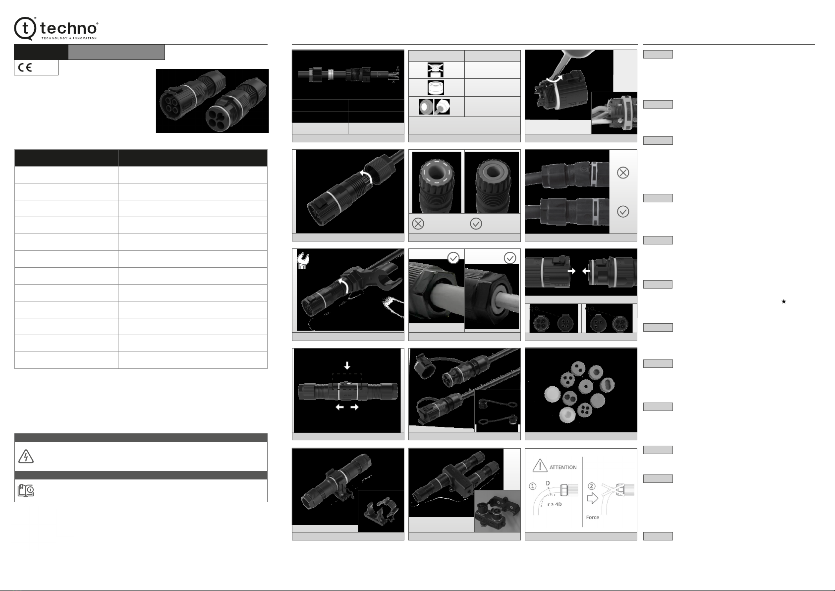
• With the aim of providing quick junction connecting solutions,Techno offers a range
of plug and socket current distributors (TH389U) compatible with TH629U
connector. Furthermore, the quick fixing base is available Fig. 11a (for more
information visit www.techno.it).
• The TH629U IP68 current distributor is a quicker solution then conventional junction
boxes and cable glands (for more information visit the website www.techno.it).
FIG. 12
• In case the connector is installed in small spaces with the need to bend the cable,
make sure of the minimum bending radius which must be ≥ 4D (D = cable diameter).
• Make sure the cable is not subject to external forces that tend to bend it. This
phenomenon can compromise the functioning of the product and in particular it
could affect the resistance to the entry of dust and water.
SAFETY NOTES
•Disconnect the power supply before starting the assembly.
•To prevent dust and humidity / water from compromising the operation of the product,
we recommended to use protective caps when the connectors are not connected
(visit www.techno.it for more information).
The connector has with live parts!
The connector is manufactured in compliance with electrical and safety regulations.
It is the responsibility of those who assemble and install it to comply with the safety
requirements of the system and ensure adequate protection from live parts.
ATTENTION
DOCUMENT CODE: 606002042 © TECHNO s.r.l.
Potential improvements of the product and modications of the technical data contained in this document can be made without notice.
Contact our Customer Service or visit our website www.techno.it to nd out about the latest updates.
INSTALLATION ILLUSTRATIONS INSTALLATION INSTRUCTIONS
FIG. 7
FIG. 10
FIG. 3
FIG. 5FIG. 4
FIG. 8
FIG. 11
FIG. 2
FIG. 3a
FIG. 6a
FIG. 9
FIG. 12
FIG. 2a
0.8 Nm
max. 2.0 Nm
max. 2.5 Nm
Visible ringNo visible ring
24 mm
FIG. 1b
Cable ø 7.0 - 13.0 mm
Insulator removal (X) 25 mm
Peeling of the conductor (Y) 6 mm
FIG. 1
Scan the QR code and watch the installation video.
Read the assembly instructions carefully before assembly and installation!
The correct functioning of the product is guaranteed only if these assembly instructions
are read and applied carefully.
NOTE
FIG. 6b
Grommet / Adapter Cable ø min. - max.
ø 9.0 - 13.0 mm
7.0 mm - 9.0 mm
with 6000087LF
6.0 mm - 7.0 mm
(1) For cables with a smaller diameter, use the appropriate
accessories (visit www.techno.it)
FIG. 3b
FIG. 6
FIG. 11a
Scan the QR code for more information.


