Technicolor NTSC-8 Manuel utilisateur

© 2016 Technicolor. All Rights reserved
Technicolor NTSC-8
User’s Manual

w w w . t e c h n i c o l o r . c o m / m c s
Page 1
Table of Contents
1Introduction................................................................................................................................. 4
2Front Panel Connections ............................................................................................................. 4
3Power Supply .............................................................................................................................. 5
4Physical Connections .................................................................................................................. 6
5COM46 Software Requirements and Setup................................................................................ 8
6NTSC-8 Setup............................................................................................................................. 9
6.1 Setting up Multiple Chassis....................................................................................................... 10
6.2 Setting the Modulator Output Channels.................................................................................... 13
6.3 Using Internal Attenuation........................................................................................................ 15
6.4 Carrier ON................................................................................................................................. 17
6.5 Sharpness................................................................................................................................... 17
6.6 Reset.......................................................................................................................................... 17
6.7 Audio Level............................................................................................................................... 18
6.8 Aspect Ratio.............................................................................................................................. 18
6.9 Verification of Streams ............................................................................................................. 18
7Software Upgrade...................................................................................................................... 19
8Status Lights.............................................................................................................................. 20

w w w . t e c h n i c o l o r . c o m / m c s
Page 2
Table of Figures
FIGURE 1-NTSC-8 FRONT PANEL...................................................................................................... 4
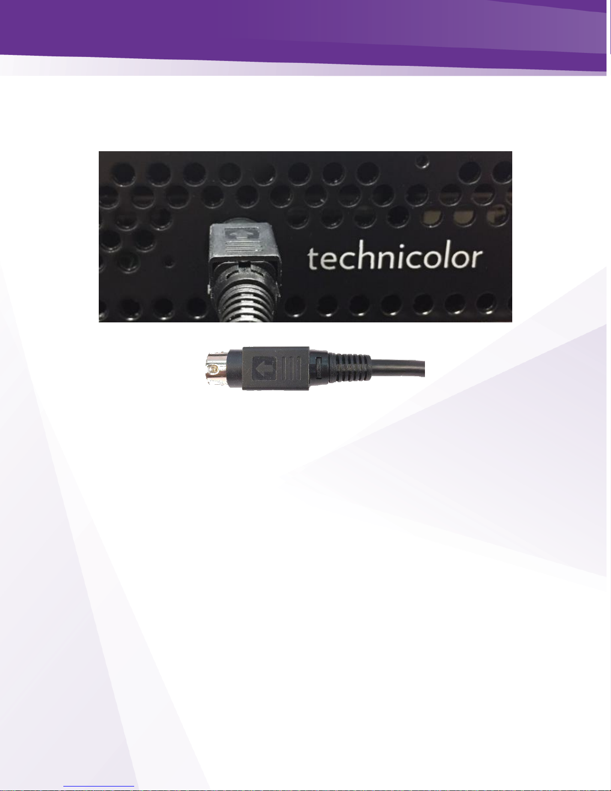
FIGURE 2-POWER SUPPLY.................................................................................................................. 5
FIGURE 3-PHYSICAL CONNECTIONS................................................................................................... 6
FIGURE 4-POWER SUPPLY CONNECTIONS .......................................................................................... 7
FIGURE 5-COM46 PAIRING INFO PAGE ............................................................................................. 8
FIGURE 6-COM46 USER CONFIG....................................................................................................... 8
FIGURE 7-COM46 MAIN INTERFACE PAGE........................................................................................ 9
FIGURE 8-COM46 NTSC TAB........................................................................................................... 9
FIGURE 9NTSC-8 MODULATOR IP................................................................................................... 10
FIGURE 10 -ENTER ALTERNATE IP ADDRESS.................................................................................... 11
FIGURE 11 -ALTIP............................................................................................................................. 11
FIGURE 12 –CHASSIS DIPSWITCH...................................................................................................... 12
FIGURE 13 -DIPSWITCH SETTINGS..................................................................................................... 12
FIGURE 14 -OUTPUT CHANNEL SETTINGS......................................................................................... 13
FIGURE 15 -STATUS PAGE SHOWING SET CHANNELS ....................................................................... 13
FIGURE 16 -CHANGING OUTPUT CHANNEL BY MODULATOR............................................................ 14
FIGURE 17 -CHANNELS SET IN STATUS TABLE ................................................................................. 15
FIGURE 18 -SET ATTENUATION IN ALL MODULATORS...................................................................... 15
FIGURE 19 CHANGING ATTENUATION ON A SINGLE MODULATOR..................................................... 16
FIGURE 20 -CARRIER ON/OFF............................................................................................................ 17
FIGURE 21 -BYTESRECIEVED ............................................................................................................ 18
FIGURE 22 -COM46 TFTP FEATURE ON PAIRING INFO PAGE .......................................................... 19
FIGURE 23 -NTSC-8 SOFTWARE UPDATE......................................................................................... 19
FIGURE 24 -SOFTWARE VERSION IN STATUS TABLE ......................................................................... 20
FIGURE 25 -LED STATUS DEFINITIONS............................................................................................. 20

w w w . t e c h n i c o l o r . c o m / m c s
Page 3
REVISION RECORD
Revision
Date
Revision Editor
Revision Description
1
11/3/16
Angelo Peruch
Final Draft Approved
1.1
11/10/16
Angelo Peruch
Revised chassis table

w w w . t e c h n i c o l o r . c o m / m c s
Page 4
1Introduction
The NTSC-8 accepts encrypted video signals from a COM46 card via Ethernet, and modulates
those eight signals as analog NTSC, standard definition, unencrypted RF channels. One NTSC-8
will modulate eight channels from one COM46 card.
Connecting multiple NTSC-8s to a COM360 chassis using a Gigabit Ethernet switch (not included)
The system offers all the advantages of a COM2000 system including remote management, and is
expandable to high definition for cost effective upgrades in the future.
System requires one RU of rack space.
Ventilation fans are rear mounted. The front and rear areas of the NTSC-8 should be kept clear to
ensure good airflow.
Included in the box is the NTSC-8 unit and power supply.
Note: Technicolor only supports NTSC-8 installations when interfaced to COM46 cards in a
COM360 chassis.
2Front Panel Connections
All connections to the NTSC-8 are on the front panel as shown in Figure one above.
Figure 1 - NTSC-8 Front Panel
Ethernet Port
Power Input Port
RF Connector
Status Lights

w w w . t e c h n i c o l o r . c o m / m c s
Page 5
3Power Supply
An external AC adaptor is included with the NTSC-8. The power adapter has a locking connector
that clicks when properly seated as shown below in Figure 2.
Figure 2 - Power Supply

w w w . t e c h n i c o l o r . c o m / m c s
Page 6
4Physical Connections
Figure 3 below details the connection of two NTSC-8 units connected to a COM2000 system. If
more than one unit is to be connected, a gigabit Ethernet switch (not included) is required between
a chassis GbE port and the NTSC-8s.
Connect remote management directly to an unused COM360 GbE port or to the GiGe switch.
To RF Distribution
Remote
Management
Device
Figure 3 - Physical Connections

w w w . t e c h n i c o l o r . c o m / m c s
Page 7
Connect the Power Cord
Carefully insert the power cord into the Power port on the NTSC-8 as shown in Figure 4. When
properly seated in the power port the plug will snap into place with an audible click. To remove,
firmly pull back on the cover and remove the plug from the power port.
Figure 4 - Power Supply Connections

w w w . t e c h n i c o l o r . c o m / m c s
Page 8
5COM46 Software Requirements and Setup
5.1 Software Requirements
COM46 cards need to be running software to version ST03.03.15 or later. You can verify software
version from the COM46 Pairing information page as shown below in Figure 5.
Figure 5 - COM46 Pairing Info Page
See COM2000 integrators manual or consult with your distributor if you need assistance upgrading
software.
5.2 COM46 Setup
Each COM46 card will stream eight channels to the NTSC-8. You will need to enter the IP
address of the first NTSC-8 modulator in the COM46 advanced edit page as shown below in
Figure 6. By default, the NTSC-8 IP addresses are set to 192.168.5.1 / 8.
Enter the IP address of the first modulator in the NTSC-8 in the NTSC8_IP field. Click Submit
Repeat in each COM46 card that is associated with a NTSC-8 unit.
(See section 5.1 below for setting up the NTSC-8).
Figure 6 - COM46 User Config
Once you have all the NTSC-8s and COM46s set up retune the channels or restart the COM 46
cards.
Enter NTSC-8 modulator 1 IP address
Submit
COM46 Software Version

w w w . t e c h n i c o l o r . c o m / m c s
Page 9
6NTSC-8 Setup
To access the NTSC user interface click on the NTSC tab as shown below in Figure 7 and Figure 8.
Note the box to the right of each field in the Control section. Checking this box will apply that
setting to all modulators in the NTSC-8.
Figure 7 - COM46 Main Interface Page
Figure 8 - COM46 NTSC Tab
Click box to apply setting to all
modulators
Table des matières


