TDK-Lambda CCG15 Series Manuel utilisateur

INSTRUCTION MANUAL
CCG15
・
30
Series
TDK-Lambda
<Page>
BEFORE USING THE POWER SUPPLY
Be sure to read this instruction manual thoroughly before using this product. Pay attention to all cautions and warnings before
using this product. Incorrect usage could lead to an electrical shock, damage to the power supply or a fire hazard.
DANGER
Never use this product in locations where flammable gas or ignitable substances are present.
INSTALLATION WARNING
·When installing, ensure that work is done in accordance with the instruction manual. When installation is improper, there is
risk of electric shock and fire.
·Installation shall be done by Service personnel with necessary and appropriate technical training and experience. There is a
risk of electric shock and fire.
·Do not cover the product with cloth or paper etc. Do not place anything flammable around. This might cause damage, electric
shock or fire.
WARNING on USE
·Do not touch this product or its internal components while circuit in operation, or shortly after shutdown. You may receive a
burn.
·While this product is operating, keep your hands and face away from it as you may be injured by an unexpected situation.
·There are cases where high voltage charge remains inside the product. Therefore, do not touch even if they are not in operation
as you might get injured due to high voltage and high temperature. You might also get electric shock or burn.
·Do not make unauthorized changes to this product nor remove the cover as you might get an electric shock or might damage
the product. We will not be held responsible after the product has been modified, changed or disassembled.
·Do not use this product under unusual condition such as emission of smoke or abnormal smell and sound etc. Please stop using
it immediately and shut off the product. It might lead to fire and electric shock. In such cases, please contact us. Do not
attempt repair by yourself, as it is dangerous for the user.
·Do not operate and store these products in environments where condensation occurs due to moisture and humidity. It might
lead fire and electric shock.
·Do not drop or apply shock to this product. It might cause failure. Do not operate these products mechanical stress is applied.
CAUTION on MOUNTING
·Confirm connections to input terminals, output terminals and signal terminals are correct as indicated in the instruction manual
before switching on.
·Input voltage, Output current, Output power, ambient temperature and ambient humidity should be kept within specifications,
otherwise the product will be damaged or malfunction.
·Input line and output line, please use the wires as short and thick as possible.
·Do not use this product in special environment with strong electromagnetic field, corrosive gas or conductive substances and
direct sunlight, or places where product is exposed to water or rain.
·Mount this product properly in accordance with the instruction manual, mounting direction and shall be properly be ventilated.
·Please shut down the input when connecting input and output of the product.
·When installing in environment where conductive foreign, dust and liquid may be present, please consider penetration of
above foreign material in the power supply by installing filter, to prevent trouble or malfunction.
1/23 C266-04-11F
CCG15
・
30 Series
Instruction Manual

INSTRUCTION MANUAL
CCG15
・
30
Series
TDK-Lambda
<Page>
2/23
CAUTION on USE
·Product individual notes are shown in the instruction manual. If there is any difference with common notes, individual notes
shall have priority.
·Before using this product, be sure to read the catalog and instruction manual. There is risk of electric shock or damage to the
product or fire due to improper use.
·Input voltage, Output current, Output power, ambient temperature and ambient humidity should be kept within specifications,
otherwise the product will be damaged, or cause electric shock or fire.
·For products without built-in protection circuit (element, fuse, etc.), insert fuse at the input to prevent smoke, fire during
abnormal operation.
·For externally mounted fuse do not use other fuses aside from our specified and recommended fuse.
·This product was made for general purpose electronic equipment use and is not designed for applications requiring high safety
(such as extremely high reliability and safety requirements. Even though high reliability and safety are not required, this
product should not be used directly for applications that have serious risk for life and physical safety. Take sufficient
consideration in fail-safe design (such as providing protective circuit or protective device inside the system, providing
redundant circuit to ensure no instability when single device failure occurs).
·When used in environments with strong electromagnetic field, there is possibility of product damage due to malfunction.
·When used in environment with corrosive gas (hydrogen sulfide, sulfur dioxide, etc.), there is possibility that they might
penetrate the product and lead to failure.
·When used in environments where there is conductive foreign matter, dust or liquid, there is possibility of product failure or
malfunction.
·Provide countermeasure for prevention of lightning surge voltage as there is risk of damage due to abnormal voltage.
·Take care not to apply external abnormal voltage to the output terminals and signal terminals. Especially, applying reverse
voltage or overvoltage more than the rated voltage to the output might cause failure, electric shock or fire.
·Never operate the product under overcurrent or short circuit condition. Insulation failure, or other damages may occur.
·The application circuits and their parameters are for reference only. Be sure to verify effectiveness of these circuits and their
parameters before finalizing the circuit design. Moreover, we will not be responsible on application patent or utility model.
·Excessive stress could cause damage. Therefore, please handle with care.
·Use recommended external fuse to each products to ensure safe operation and compliance with the Safety Standards to which
it is approved.
·The input power source to this product must have reinforced or double insulation from the mains.
·This product has possibility that hazardous voltage may occur in output terminal depending on failure mode. The output of
these products must be protected by over voltage protection circuit in the end use equipment to maintain SELV.
Note
·Consider storage of the product at normal temperature and humidity avoiding direct exposure to sunlight at environment with
minimal temperature and humidity changes. Storage of product at high temperature, high humidity and environments with
severe changes in temperature and humidity might cause deterioration, and occurrence of condensation in the product.
·When disposing product, follow disposal laws of each municipality.
·Published EMI (CE, RE) or immunity is the result when measured in our standard measurement conditions and might not
satisfy specification when mounted and wired inside end-user equipment.
·Use the product after sufficiently evaluating at actual end-user equipment.
·If products are exported, please register the export license application etc. by the Government of Japan according to Foreign
Exchange and Foreign Trade Control Law.
·The information in the catalog or the instruction manual is subject to change without prior notice. Please refer to the latest
version of the catalog or the instruction manual.
·No part of this document may be copied or reproduced in any form without prior written consent TDK-Lambda.

INSTRUCTION MANUAL
CCG15
・
30
Series
TDK-Lambda
<Page>
1. Model name identification method
CCG 30 – 24 – 05 S / □
Option(*1) (*1) Blank :Standard
/P :Remote ON/OFF
Positive Logic
Symbol for number of output S:Single Output
D:Dual Output
Output Voltage
Input Voltage
Output Power type
Series Name
2. Terminal Explanation
Top view
Bottom view
3/23
CCG-S
① +Vin : +Input Terminal
② -Vin : -Input Terminal
③ RC : Remote ON/OFF Control Terminal
④ +Vout : +Output Terminal
⑤ TRM : Output Voltage Trimming Terminal
⑥ -Vout : -Output Terminal
①
②
③ ⑥
⑤
④
CCG-D
① +Vin : +Input Terminal
② -Vin : -Input Terminal
③ RC : Remote ON/OFF Control Terminal
④ +Vout : +Output Terminal
⑤ COM : Common Ground Terminal
⑥ -Vout : -Output Terminal
Name Plate
④
⑤
⑥
②
①
③

INSTRUCTION MANUAL
CCG15
・
30
Series
TDK-Lambda
<Page>
4/23
3. Block Diagram
CCG30-S
CCG15-S
CCG-D
Rectifier Circuit
or
Synchronous
Rectifier Circuit
Switching Frequency(fixed) : 430kHz
+Vin
Remote
ON/OFF
Control
-Vin
RC
+Vout
-Vout
TRM
*3.3V,5V Model only
Input Filter
Input Voltage
Detector
OCP
SwitchingControl Circuit
Bias Power
Supply
Bias Power
Supply
Driver Circuit
Output Voltage
Detector
Output Filter
Rectifier Circuit
or
Synchronous
Rectifier Circuit
Switching Frequency(fixed) : 3.3V、 5V : 270kHz
12V、 15V : 360kHz
+Vin
Remote
ON/OFF
Control
-Vin
RC
+Vout
-Vout
TRM
*3.3V,5V Model only
Input Filter
Input Voltage
Detector
OCP
SwitchingControl Circuit
Bias Power
Supply
Bias Power
Supply
Driver Circuit
Output Voltage
Detector
Output Filter
Switching Frequency(fixed) : 430kHz
+Vin
Remote
ON/OFF
Control
-Vin
RC
+Vout
-Vout
COM
Rectifier Circuit
Input Filter
Switching
Input Voltage
Detector
OCP
Control Circuit
Bias Power
Supply
Output Filter
Output Voltage
Detector

INSTRUCTION MANUAL
CCG15
・
30
Series
TDK-Lambda
<Page>
5/23
4. Sequence Time Chart
*1 For example on above, RC Voltage shows Negative Logic control operation. For details on this function,
please refer to Application Notes “6-7. Remote ON/OFF Control (RC terminal)” section.
RC
Voltage
(*1)
Vin
0V
Vout
0V
Hi
Low
Input
Voltage
Output
Voltage
Input ON
OCP set point
Input OFF
Input ON
Remote ON
OCP reset
OCP trip
Remote OFF

INSTRUCTION MANUAL
CCG15
・
30
Series
TDK-Lambda
<Page>
6/23
5. Terminal Connecting Method
In order to use the CCG series, this power supply must be connected with external components
according to Fig.5-1.
If it is connected to wrong terminal, the power supply will be damaged. Pay attention to each wiring.
Fig.5-1 Basic connection
F1 : Input Fuse
CCG series has no internal fuse.
Use external fuse to comply various Safety Standards and to improve safety.
Moreover, use fast-blow type for every power supply.
Furthermore, fuse must be connected to +Vin side if -Vin side is used as ground, or fuse must be
connected to -Vin side if +Vin side is used as ground.
Consider margin over the actual input voltage to be used when selecting fuse. Moreover, consider
I2t fuse rating for surge current (inrush current) during line throw-in.
Input Fuse Recommended Current Rating
CCG15-24-xxS/D : 6.3A or lower
CCG15-48-xxS/D : 5.0A or lower
CCG30-24-xxS/D : 10A or lower
CCG30-48-xxS/D : 6.3A or lower
CCG-S
+Vin
RC
+Vout
-Vout
C1
-Vin
LoadTRM
F1
+
-
Vin
CCG-D
+Vin
RC
+Vout
-Vout
C1
-Vin
Load
COM
F1
+
-Vin
Load
+
-
CCG-S
+Vin
RC
+Vout
-Vout
C1
-Vin
LoadTRM
F1
+
-
Vin
CCG-D
+Vin
RC
+Vout
-Vout
C1
-Vin
Load
COM
F1
+
-Vin
Load
+
-
(a) Standard model (Negative Logic model)
(b) Positive Logic model

INSTRUCTION MANUAL
CCG15
・
30
Series
TDK-Lambda
<Page>
7/23
C1 : External Input Capacitor
To prevent the effect of input line inductance to the power supply, connect electrolytic capacitor
between +Vin and -Vin terminals.
Recommended Capacitance
CCGxx-24-xxS/D : 120μF or more
CCGxx-48-xxS/D : 47μF or more
Note) 1.Use low impedance electrolytic capacitor with excellent temperature characteristics.
(Nippon Chemi-Con KZE series or equivalent)
2.When using CCG15-24-xxS below -10℃ ambient temperature, connect more than two
recommended capacitor in parallel to reduce ESR.
3.When input line inductance becomes excessively high due to insertion of choke coil,
operation of the power supply could become unstable. For this case, increase capacitance
of electrolytic capacitor more than recommended capacitance.
4.When steeply to open the input line by using the relay etc. when the power supply is operating,
there is possibility of the power supply restarts due to the power input voltage rises.
It is influenced by the impedance characteristics of pattern on printed circuit board, C1 and choke
coil etc.
Please use it on the actual machine sufficiently.
INSTRUCTION MANUAL
CCG15
・
30
Series
TDK-Lambda
<Page>
8/23
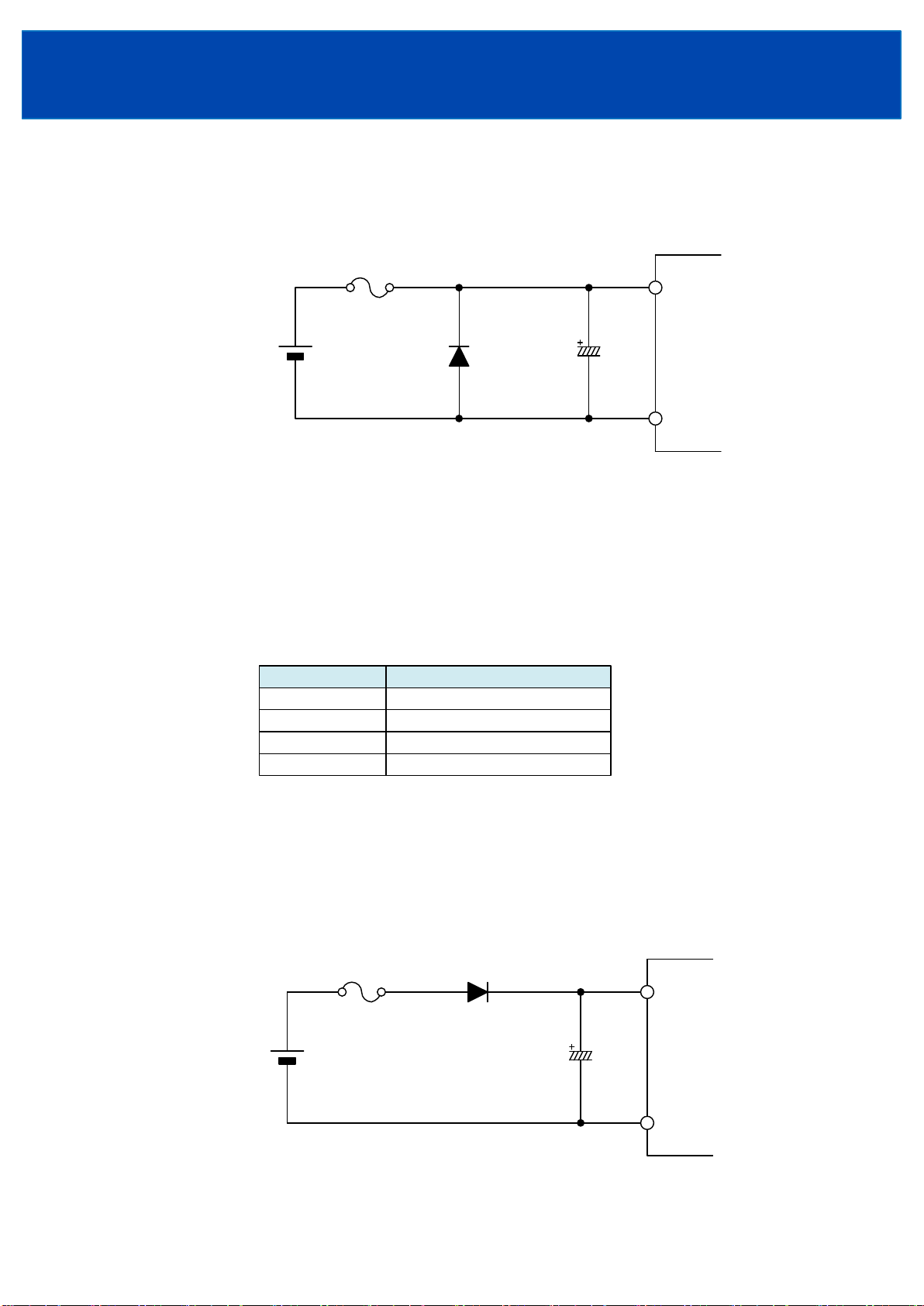
Fig.5-3 Caution about Connecting Output Capacitor
C1
F1
+Vin
-Vin
Input Voltage
Retention Diode
Vin
● Protection for Reversed Input Connection
Reverse input polarity would cause power supply damage. For cases where reverse connections
are possible, connect a protective diode and fuse. Use protective diode with higher voltage rating
than the input voltage, and with higher surge current rating than fuse current rating.
● External Output Capacitor
This power supply is capable of operating without external output capacitor.
For case of abrupt changes in load current or the line to the load is long, operation might become
unstable. In this case, it is possible to stabilize the output voltage by attaching capacitor.
CCG-S : between +Vout and -Vout terminal
CCG-D : between +Vout and COM terminal, -Vout and COM terminal
Maximum capacitance of external output capacitor is shown in Table 5-1.
Note) When using 3.3V and 5V output models of CCG30-S, output voltage might become unstable at
input voltage dips or short interruption on connection output capacitor. In this case, it is possible
to stabilize the output voltage by attaching input voltage retention diode and increase capacitance
of C1 as shown in Fig.5-3. Use input voltage retention diode with higher current rating than fuse
current rating. Moreover, choose a suitable capacitance of C1 in accordance with operating
condition.
Table 5-1 Maximum Capacitance of External Output Capacitor
Fig.5-2 Protection for Reversed Input Connection
C1
F1
+Vin
-Vin
Protective
Diode
Vin
Model
3.3V
5V
Maximum capacitance
10,000μF
7,200μF
12V, ±12V
15V, ±15V
1,200μF
1,000μF

INSTRUCTION MANUAL
CCG15
・
30
Series
TDK-Lambda
<Page>
9/23
6-2. Output Voltage Adjustment Range (Only CCG-S)
Output voltage could be adjusted within the range described below by connecting external resistor
or variable resistor.
However, take note that power supply might be damaged when output voltage exceeds the range
described below.
When increasing the output voltage, reduce the output current accordingly so as not to exceed the
maximum output power.
Take note that when output voltage is decreased, maximum output current is until rated maximum
output current of specification.
Output Voltage Adjustment Range : ±10% of Nominal Output Voltage
6. Explanation of Functions and Precautions
6-1. Input Voltage Range
Input voltage range for CCG series is indicated below.
Input Voltage Range
CCGxx-24-xxS/D : 9 - 36VDC
CCGxx-48-xxS/D : 18 - 76VDC
Take note that power supply might be damaged or not meet specification when applied input voltage
which is out of specified range.
Ripple voltage(Vrpl) which results from rectification and filtering of commercial AC line is might be
included within the input voltage as shown in Fig.6-1.
In this case, ripple voltage must be limited within the voltage described below.
Allowable Input Ripple Voltage:2Vp-p
When input ripple voltage exceed above value, the output ripple voltage might be large.
Take note that sudden input voltage change might be cause variation of output voltage transitionally.
Moreover, maximum value and minimum value of input voltage waveform must not go beyond the limit
of above input voltage range.
Vrpl
2V or lower
Input Voltage
Range
Times
Input Voltage
Fig.6-1 Input Ripple Voltage

INSTRUCTION MANUAL
CCG15
・
30
Series
TDK-Lambda
<Page>
10/23
● Output Voltage Adjustment by External Resistor or Variable Resistor (Only CCG-S)
(1) In case of adjusting output voltage lower
(1-1) Maximum output current
In case of adjusting output voltage lower, maximum output current is until rated maximum
output current of specification.
ex)In case of CCG30-xx-12S
When setting 12V Model to 10.8V output, maximum output power = 10.8V×2.5A = 27W.
(1-2) External resister connecting method
Connect an external resistor or variable resister Ra between TRM and +Vout terminal.
To prevent the effect of noise or other, connect as short as possible because TRM terminal is
relatively high impedance.
Please refer to Table 6-1 when adjusting output voltage.
Output Voltage:Vout(V), External Resistor Value:Ra(kΩ)
Output voltage could be adjusted within the -10% of nominal output voltage
by external resistor Ra.
Fig.6-2 Basic Connection for Output Voltage Trim Down
Table 6-1 Equation of External Resistor and Output Voltage
+Vout
-Vout
Load
TRM
+
-
Ra
CCG-S
CCGxx-xx-03S
CCGxx-xx-05S
CCGxx-xx-12S
CCGxx-xx-15S
Model Equation
Vout (V) = 3.3 - 16.05
22.8+Ra (kΩ)
Vout (V) = 5.01 - 53.95
32.3+Ra (kΩ)
Vout (V) = 12.05 - 445.7
63.1+Ra (kΩ)
Vout (V) = 15.08 - 732.7
74.7+Ra (kΩ)
Ra (kΩ)= 22.8-
16.05
3.3-Vout (V)
Ra (kΩ)= 32.3-
53.95
5.01-Vout (V)
Ra (kΩ)= 63.1-
445.7
12.05-Vout (V)
Ra (kΩ)= 74.7-
732.7
15.08-Vout (V)
Ce manuel convient aux modèles suivants
1
Table des matières
Autres manuels TDK-Lambda Convertisseur de média

TDK-Lambda
TDK-Lambda EZA2500 Series Instructions d'utilisation d'origine

TDK-Lambda
TDK-Lambda Vega DC Manuel utilisateur

TDK-Lambda
TDK-Lambda EZA 2500 - 32048 Manuel utilisateur

TDK-Lambda
TDK-Lambda EZA11K Series Guide d'installation

TDK-Lambda
TDK-Lambda PYH200 Series Manuel utilisateur

TDK-Lambda
TDK-Lambda EZA11K Series Guide d'installation

TDK-Lambda
TDK-Lambda RFE1600 Series Manuel utilisateur

TDK-Lambda
TDK-Lambda PH Series Manuel utilisateur

TDK-Lambda
TDK-Lambda CC15-xxxx-Sxx-E Series Manuel utilisateur

TDK-Lambda
TDK-Lambda CCG Series Manuel utilisateur


