TAS APFC-06 04 Manuel utilisateur

Automatic Power Factor Controller
for L.T. Applications
APFC-06/xx
xx =04/06/08/ 2 Relay Output Channels
User Manual
First Release Date: 6th April 20 8.
Updated on: 7th February. 2022.

Power Factor Controller APFC 06
NOTE
These instructions do not purport to cover all details or variations in equipment, nor to
provide for every possible contingency to be met in connection with installation,
operation or maintenance.
Should further information be desired or should particular problems arise which are not
covered sufficiently for the purchasers purposes, the matter should be referred to TAS
office.
The contents of this instruction Manual shall not become part of or modify any prior or
existing agreement or relationship. Any statements contained herein do not create new
warranties or modify the existing warranty.
The reproduction, transmission or use of this document or its contents is not permitted
without express written authority. Offenders will be liable for damages.
All rights are reserved.
ecause of continuous improvements efforts by TAS in their Product’s Features and
Specifications, the Product as well as the content of the User Manual is likely to get
updated.
Therefore, please always refer to the User Manual supplied to the customer along with
the Product, at the time of product dispatch.
the Product, at the time of product dispatch.
CAUTIONS:
• There are High Voltages associated with this Unit, so, take appropriate
precautions.
• This Automatic Power Factor Controller (APFC) is for only in-door use.
• Make sure that the discharge time set in the controller matches with the
capacitor bank discharge time.
Please always refer to the User Manual supplied to the customer along with the
Product, at the time of product dispatch, or check from us or from our website.
A short-form User Guidelines Manual is being supplied with the TAS APFC-06
Unit for quick information and settings during field installation by the User.
Please refer to full version of the User Manual for more detailed understanding
and use of our Automatic Power Factor Controllers. Check TAS website,
www.taspowertek.com for the availability of the User Manual under appropriate
sections / down-loads section.
This User Manual corresponds to the APFC-06/xx Controller, Firmware
Version 2.1.1 Dated: 16th Feb. 2021.

Index
Index page -- 1
Features -- 2
Specifications -- 3
Mechanical dimensions -- 4
Front fascia -- 5
Rear side terminals -- 6
F correction technique -- 7 & 8
Typical wiring scheme -- 9
Control wiring scheme -- 10
Front fascia LCD screen details -- 11 & 12
Keyboard details -- 13
Display of various parameters -- 14
Sub
-
menu for display of parameters
--
15
Power Factor Controller APFC 06
- 1 -
Sub
-
menu for display of parameters
--
15
Method of Keyboard / display usage -- 16 to 18
Keyboard / display operations -- 19 & 20
Edit arameters -- 20
General & IO -- 21
System -- 21
Fault -- 22 to 24
Steps -- 25 & 26
Utilization Counters -- 27
Commissioning instructions -- 28 & 29
Troubleshooting procedure -- 30
Edit arameters :Min., Max., -- 31 to 35
Default Values
Blank forms for Field User Entries -- 36 to 40
Important Notes -- 41

Features:
•32-Bit ARM Cortex-Mx State-of-the-Art Technology
Micro-Controller controlled Digital Signal rocessing logic for
measurements, monitoring, indication, alarming & controls.
•ower Measurements with Class-3 accuracy as IEC62053-
pt21 & 23.
Auto CT polarity check (user editable)
•hase-to- hase Measurement Voltage Feedback on
independent Input Terminals.
•Single CT Supply (Load) Current Measurement Feedback on a
Three-Terminal Side Connector at the Rear.
•Supply V, I, odd harmonic coefficients up to 15th Harmonic.
•Wide AC I/ Voltage Range measurement.
•Various modes for switching, viz.:
Un
-
equal (user defined)
Power Factor Controller APFC 06
Un
-
equal (user defined)
C-Series (preset series)
E-Series (user defined)
•Output Capacitor Banks control:
4 or 6 or 8 or 12 Banks, as per ordered Model.
•Auxiliary Digital Input (N.O. Contact) and Auxiliary Digital
Output ( otential-Free N.O. Relay Contact, for external
systems Interlocks, or Auxiliary Digital Output for A FC anel
Cooling Fan On / Off Control, if enabled.
•16-Char. x 2-Lines, LCD Display with LED Back-light.
•DIN Standard 144mmX144mm Metal Cabinet for panel-door
flush-mounting.
•rotections provided:
Over / Under supply voltage
Over current / under load (kW)
Over Temperature of A FC Unit
Capacitor Bank Step health-check
All are user settable.
- 2 -

Specifications:
• Feed-back Voltage: 1- h, 2-wire ( hase-to- hase), Nom. 415 Volts.
(User Settable Range: 110 to 480 Vac, in step of 1 Volt).
• Supply Current Feedback (CT) I/ : Selectable Nom. 1 Amp or 5 Amp.
• Measurement Accuracy: Class 2.
• Auxiliary Operating Supply: 1- h, 2-wire ( hase-to- Neutral),
Nominal 240 Volts, 50 Hz, or Nominal 120 Volts, 60 Hz.
• Feed-back Voltage and Mains AC Supply Frequency Range:
47 Hz to 53 Hz. (Nom. 50 Hz) or 57 Hz to 63 Hz (Nom. 60 Hz).
• . F. Correction Cycle Time Range:
User Selectable:1 Second to 600 Seconds, in step of 1 Second.
•
Capacitor Bank Discharge Time Range:
Power Factor Controller APFC 06
•
Capacitor Bank Discharge Time Range:
User Selectable:1 Second to 600 Seconds, in step of 1 Second.
• Output commands: 4 or 6 or 8 or 12 Relay N.O. Contacts Outputs.
(Isolated ‘N.O.’ Relay Contacts of rating 5 Amp (Resistive Load) /
0.5Amp (Inductive Load)/ 230Vac, suitable for Three- hase
Capacitor-Duty Contactor Coils of nominal 230 Vac, 50 Hz).
• Operating Temperature Range: +5oC. to +60oC.
• Class-2 power measurement accuracy operating temp.
+5oC to +50oC
• Storage Temperature Range: -5oC to +65oC.
• Relative Humidity Range: 10% to 90% RH Non-Condensing.
- 3 -
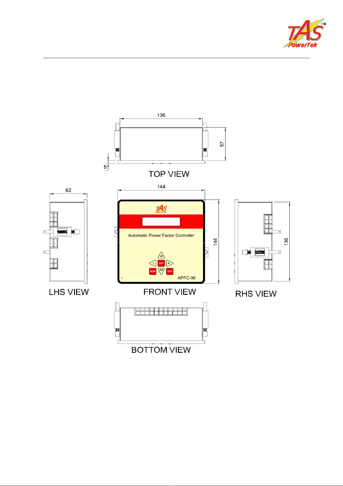
Mechanical dimensions:
Power Factor Controller APFC 06
- 4 -
Recommended size for cutout on panel door: 138 mm x 138 mm.
Maximum weight: (with mounting clamps) = 0.8 kg approx.
Note: Low-Depth behind the A FC anel Door, being a slim model!
All Dimensions are in mm.

Front fascia:
Keyboard, LCD Display
LCD Display with LED Back-Light having Auto-On/Off
Power Factor Controller APFC 06
PF= 1.00 IND A OKPF= 1.00 IND A OK
- 5-
7-Keys Key-pad

Rear side terminals
Measurement
Feedback
Voltage
Supply current
Feedback CT,
User Selection of
1 Amp or 5 Amp
Nominal &
Common
Power Factor Controller SPF
Auxiliary Digital Outputs –
Potential-free, N.O. Relay Contact,
Contact Rating: 5A (Resistive), 240Vac
nominal
Auxiliary
Digital
Input,
Connect
APFC - 06
- 6 -
Voltage
(Rated Nom.
380-485 Vac,
50 / 60 Hz).
Output terminals
Output commands to capacitor contactors.
COM = common,
C1….C12 ( C4 or C6 or C8) = potential free N.O.
contact, 5 A (Resistive Load), 250 Vac.
Auxiliary Operating
Voltage
Connect
N.O.
Contact
(Rated Nom. 240 Vac,
50/60 Hz. )
Use Correct Size “U” Type, Insulated Fork Lugs for Field Wires Connections,
suitable for 2.5 mm-Square wires. Suggested Make: Chetna Engg., F-57,
Ambad MIDC, Nashik-422 010, India. Cat. No.: CCFM-937, Serial No.: 835.
Or Direct Equivalent.

PF correction technique
kW.
kVAr
(Ind)
kVAr
(Cap)
PFLOWER.
PFUPPER.
-kW.
PFLOWER.
PFUPPER.
Case-1: FU ER & FLOWER both set as inductive:
smallest
Capacitor bank
kVAr x 1.5 width.
Power Factor Controller APFC 06
- 7 -
kVAr
(Ind)
kVAr
(Cap)
PFLOWER.
PFUPPER.
-kW
PFLOWER.
PFUPPER.
smallest
Capacitor bank
kVAr x 1.5 width.
Case-2: FU ER as Capacitive & FLOWER set as Inductive:
kW
No change band.
Capacitor addition band.
Capacitor removal band.

No change band.
Capacitor addition band.
Capacitor removal band.
Power Factor Controller APFC 06
kVAr
(Ind)
kVAr
(Cap)
PFLOWER.
PFUPPER.
-kW
PFLOWER.
PFUPPER.
smallest
Capacitor bank
kVAr x 1.5 width.
kW.
Case-3: FU ER & F-LOWER both set as Capacitive:
There are two F set points to be set in A FC 06. The U ER limit and
the LOWER limit. A FC 06 ensures that F-U ER is never exceeded.
Additionally, “No change band” to minimum kVAr band size equal to
smallest bank kVAr x 1.5 ensures no hunting during the low kW loading.
A FC 06 is normally set for F settings as per first two diagrams shown
where F LOWER is inductive. This philosophy helps to optimize the
system maximum kVAr to be used as well as reduces the number of
switching operations during higher loading conditions. This ensures better
life expectancies of the switched capacitors as well as the switching
devices.
This methodology of kVAr compensation reduces the complex settings
that are used by conventional F relays. The settings like C/K ratio and
kVAr offsets/shifts are eliminated which makes A FC 06 user friendly and
thus easy to commission.
- 8 -
Ce manuel convient aux modèles suivants
3
Table des matières
Autres manuels TAS Contrôleurs


