Taco Electronic Solutions iWorx MPU2 Manuel utilisateur

© 2013 Taco Electronic Solutions, Inc. 1
Installation Guide 502-009
MPU2/MPU3 Air Control – Pressure Dependent Multi-Zone
Self-Contained Interoperable Controller Model UCP-1
SUPERSEDES: May 25, 2011 EFFECTIVE: April 17, 2013
Plant ID: 001-3961
SPECIFICATIONS
Electrical Inputs
Cabling: twisted shielded pair, 18 AWG recommended—500 feet max. (152 meters), 10 bit resolution
Mixed Air Low Limit, Filter Status, Smoke Detect, Local IAQ Alarm: Dry Contact, Normally Open, 5 Volts DC Max
Fan Proof: Dry Contact, Normally Closed
Return Air Humidity, Static Pressure: 0 - 10 Volts DC
Mixed Air Temperature, Supply Air Temperature, Return Air Temperature: Precon Type III 10K thermistor
Electrical Outputs
Fan Start/Stop, Heating Stage 1, Heating Stage 2, Cooling Stage 1, Cooling Stage 2, Cooling Stage 3, Cooling Stage
4, Digital Economizer: 24 Volts AC, 1A @ 50C, 0.5A @ 60C, limited by the Class 2 supply rating
Modulated Heating, Modulated Cooling, Modulated Economizer, Bypass Damper: 0-10 Volts DC, 2K Ohm minimum
load, 8 bit resolution
Recommended Sensor Wire
Recommended LON Bus FTT-10A Network Wire
Speed: 78KBPS
Max Volts: 42.4 Volts DC
Cabling: Maximum node-to-node distance: 1312 feet (400 meters); Maximum total distance: 1640 feet (500 meters)
Mechanical
Dimensions: 5.55” (141mm) high, 6.54” (166 mm) wide, 1.75” deep (44 mm), ABS
Controller Weight: 0.70 pounds (0.32 kilograms)
Shipping Weight: 1.0 pounds (0.46 kilograms)
Processor: 3150 Neuron 10 MHz
Flash: 48 Kilobytes
SRAM: 8 Kilobytes
Termination: 0.197” (5.0 mm) Pluggable Terminal Blocks, 14-22 AWG
Cable Type Pairs Details Taco Catalog No.
18AWG 1 Stranded Twisted Shielded Pair, Plenum WIR-018
Cable Type Pairs Details Taco Catalog No.
Level 4 22AWG (0.65mm) 1 Unshielded, Plenum, U.L. Type CMP WIR-022

iWorx® MPU2/MPU3
2 502-009, Effective: April 17, 2013
© 2013 Taco Electronic Solutions, Inc.
Temperature: 32 °F to 140 °F (0 °C to 60 °C)
Humidity: 0 to 90%, non-condensing
UL Listed for US and Canada, Energy Management Equipment PAZX and PAZX7
FCC Part 15 Class A compliant
Equipment Location
Abide by all warnings regarding equipment location provided in this document. This equipment is suitable for
indoor use only. Preferably, or as required by National Electrical Code, the unit is intended to be installed within
an electrical control enclosure. Operate where ambient temperatures do not exceed 140 °F (60 °C) or fall
below 32 °F (0 °C) and relative humidity does not exceed 90%, non-condensing.
If the equipment is to be installed outdoors, it must be contained within a protective enclosure that maintains internal tem-
perature and humidity within the ranges specified for this equipment.
The equipment must be installed within 500 feet of all input peripherals (smoke detectors, sensors, etc.) that are connected
to the equipment.
Avoid locations where corrosive fumes, excessive moisture, vibration or explosive vapors are present.
Avoid electrical noise interference. Do not install near large contactors, electrical machinery, or welding equipment.
Selecting a Power Source
This equipment requires a UL recognized Class 2 external power source (not supplied) to operate. The controller power
input requires a voltage of 24 Volts AC.
To calculate power source current requirements, add the power consumption of all peripheral devices to that of the control-
ler.
The controller and sensor power supplies can use the same power source. If both are using the same power source, the
loads must have EMF protection. This protection can be integral to the load, or installed in the 24 VAC wiring across the
load’s coil.
To provide necessary RFI and transient protection, the controller’s ground (GND) pin (T40) must be connected to earth
ground or the earth ground of the packaged unit’s enclosure ground. Failure to properly ground the controller may cause it
to exceed FCC limits. Excessive noise could also produce inaccurate sensor data. The power source must be capable of
operating with this connection to ground.
INSTALLATION PRECAUTIONS
General
CAUTION: This symbol is intended to alert the user to the presence of important installation and maintenance
(servicing) instructions in the literature accompanying the equipment.
CAUTION: Risk of explosion if battery is replaced by an incorrect type. Contains lithium type battery; dispose
of properly.
WARNING: Electrical shock hazard. Disconnect ALL power sources when installing or servicing this equip-
ment to prevent electrical shock or equipment damage.
Make all wiring connections in accordance with these instructions and in accordance with pertinent national and local elec-
trical codes. Use only copper conductors that are suitable for 167 °F (75 °C).
Static Electricity
Static charges produce voltages that can damage this equipment. Follow these static electricity precautions when handling
this equipment.
• Work in a static free area.

iWorx® MPU2/MPU3
502-009, Effective: April 17, 2013 3
© 2013 Taco Electronic Solutions, Inc.
• Touch a known, securely grounded object to discharge any charge you may have accumulated.
• Use a wrist strap when handling printed circuit boards. The strap must be secured to earth ground.
FCC Compliance
This equipment has been tested and found to comply with the limits for a Class A digital device, pursuant to Part 15 of the
FCC rules. These limits are designed to provide reasonable protection against harmful interference. This equipment can
radiate radio frequency energy and, if not installed and used in accordance with the instructions, may cause harmful inter-
ference to radio communications. However, there is no guarantee that interference will not occur in a particular installation.
If this equipment does cause harmful interference to radio or television reception, which can be determined by turning the
equipment off and on, the user is encouraged to try to correct the interference by one or more of the following measures:
• Reorient or relocate the receiving antenna.
• Increase the separation between the equipment and the receiver.
• Connect the equipment to a power source different from that to which the receiver is connected.
• Consult the equipment supplier or an experienced radio/TV technician for help.
You are cautioned that any changes or modifications to this equipment not expressly approved in these instructions could
void your authority to operate this equipment in the United States.
INSTALLATION
Warning: Electrical shock hazard. To prevent electrical shock or equipment damage, disconnect ALL power
sources to controllers and loads before installing or servicing this equipment or modifying any wiring.
Mounting the Device
1.Select a mounting location. Enclosure mounting is recommended.
2.Hold the controller on the panel you wish to mount it on. With a marker or pencil mark the mounting locations on the
panel.
3.Using a small drill bit pre-drill the mounting holes.
4.Using two #6 pan head screws, mount the controller to the panel.
5.Wire the controller.
Grounding the Device
The ground terminal (T40) must be securely connected to earth ground. Failure to properly ground this equip-
ment will result in improper operation. Improper grounding may also increase the risk of electrical shock and
may increase the possibility of interference with radio/TV reception.
For best performance, connect the power supply common terminal (T38) to the same external point as the
ground terminal (T40).
Power
Requires: 24VAC (20VAC to 28VAC), requires an external Class 2 supply
Consumes: 7.2W with no external loads, maximum limited by the Class 2 supply rating

iWorx® MPU2/MPU3
4 502-009, Effective: April 17, 2013
© 2013 Taco Electronic Solutions, Inc.

iWorx® MPU2/MPU3
502-009, Effective: April 17, 2013 5
© 2013 Taco Electronic Solutions, Inc.
iWorx® MPU2/MPU3
6 502-009, Effective: April 17, 2013
© 2013 Taco Electronic Solutions, Inc.

iWorx® MPU2/MPU3
502-009, Effective: April 17, 2013 7
© 2013 Taco Electronic Solutions, Inc.
iWorx® MPU2/MPU3
8 502-009, Effective: April 17, 2013
© 2013 Taco Electronic Solutions, Inc.
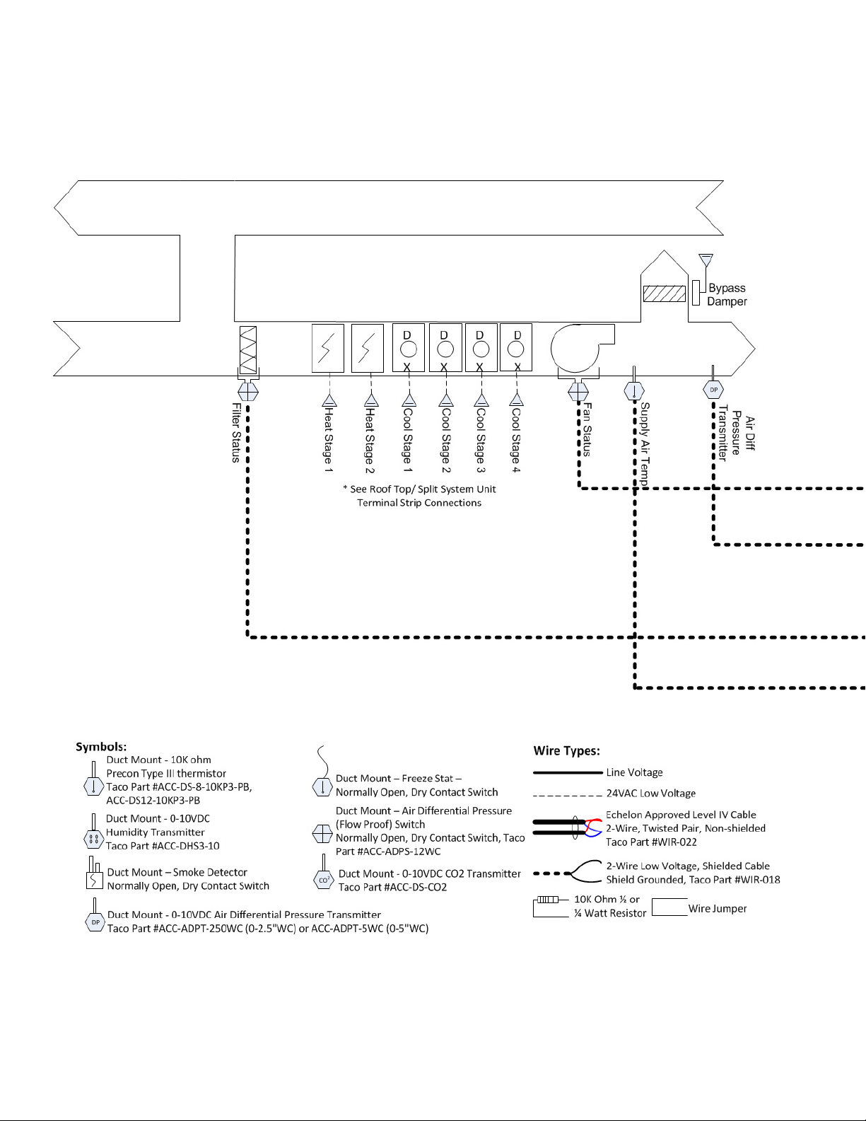
Variable Air Volume, Variable Air Temperature (VVT)
Staged Rooftop or Split System:
• 2 Stage Heating - Electric or Gas,
• 4 Stage Cooling - DX
• Modulating Pressure Bypass Damper
Sensors Required: Supply Air Temp, Fan Proof, Filter
Status, Air Differential Pressure Transmitter
Added Module Required: At least 1 VAVD (up to 32)
on Taco LON Bus
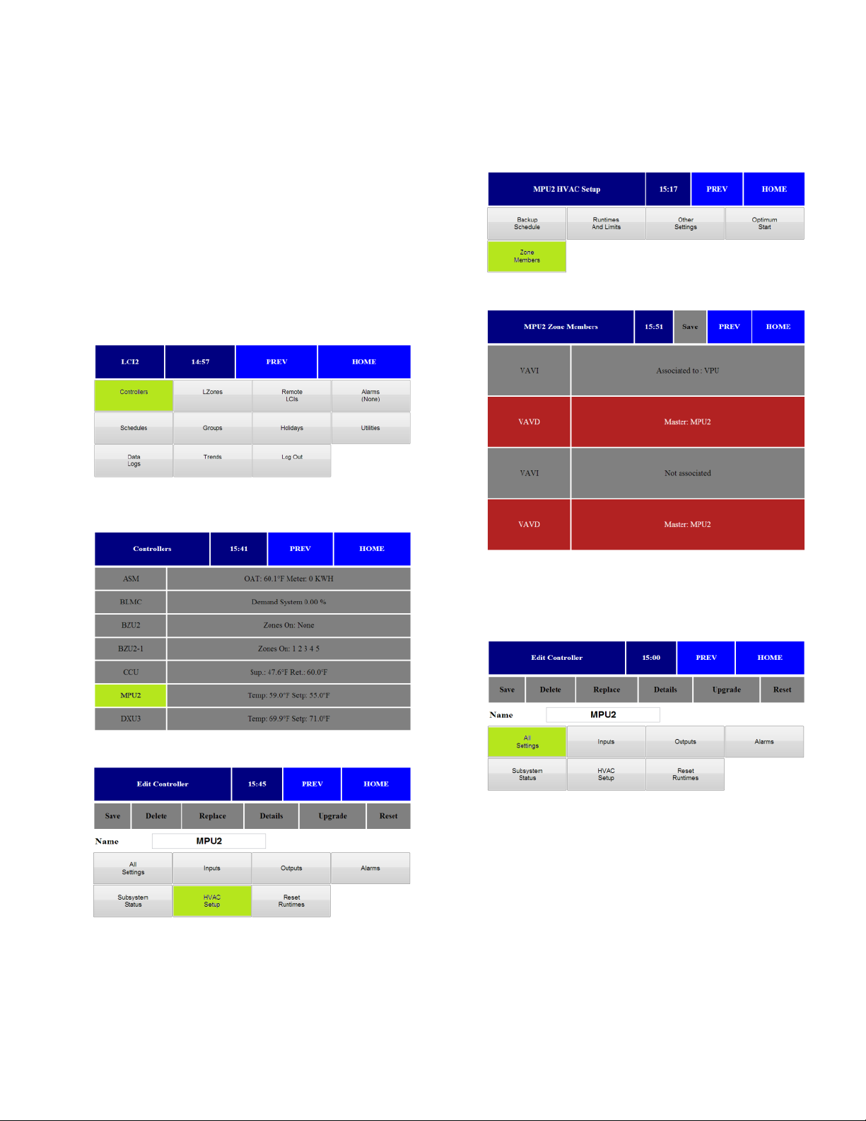
Setup Instructions
1.Press Controllers from main screen
2.Select required MPU from controller list and press
appropriate controller.
3.Press HVAC Setup.
4.The HVAC Setup menu opens. Press Zone Mem-
bers.
5.The Zone Members menu opens.
6.Press on VAV boxes associated with MPU. Associ-
ated controllers appear in RED. Press Save.
7.Press Prev twice. From the Main Controller Menu,
press All Settings.

iWorx® MPU2/MPU3
502-009, Effective: April 17, 2013 9
© 2013 Taco Electronic Solutions, Inc.
8.Press Setpoints.
9.The Setpoints menu opens.
a.Select Cooling Setpoint.
b.Select Heating Setpoint.
c. Select Supply Cool Limit (sets deviation from set-
point for alarm).
d.Select Supply Heat Limit (sets deviation from set-
point for alarm).
e.Press Save.
10.Press Supply Temp Reset Curve.
11.The Supply Temp Reset Curve menu opens.
a.Select Min Differential.
b.Select Max Differential.
c. Select Cool Setp Low.
d.Select Cool Setp High.
e.Select Heat Setp Low.
f. Select Heat Setp High.
g.Press Save.
12.Press Pressure Settings.
13.The Pressure Settings menu opens.
a.Select Static Pressure Setpoint in Inches of WC.
b.Select the IAQ Setpoint (if applicable).
c. Select Min Output Voltage (VDC) for Bypass
Damper (commonly 0-2VDC).
d.Select Max Output Voltage (VDC) for Bypass
Damper (commonly 10VDC).
e.Note: VFD Settings - If VFD drive is utilized in lieu
of bypass damper, swap the settings in steps c.
and d. above. IE: Min Output = 10VDC, Max Out-
put = 0 or 2VDC.
f. Select Press Min (Static pressure to report when
the Duct SP sensor provides 0 VDC).
g.Select Press Max (Static pressure to report when
the Duct SP sensor provides 10 VDC).
h.Press Save.
i. Note: DO NOT change factory KP/KI settings.
Please review Factory KP/KI Setting White Paper #
508-001.

iWorx® MPU2/MPU3
10 502-009, Effective: April 17, 2013
© 2013 Taco Electronic Solutions, Inc.
14.Press MPU Settings.
15.The MPU Settings menu opens.
a.Select Changeover Time (min amount of time
between changeover between heating and cool-
ing).
b.Select Zone Limit (min required zones demands
before enabling heating or cooling).
c. Press Save.
16.Press Staged Cooling.
17.The Staged Cooling menu opens.
a.Select number of stages of equipment (0-4).
b.Select the stage control band in degrees. Cannot
be set to 0.
c. Select the stage time in minutes. Cannot be set to
0.
d.Press Save.
18.Press Staged Heating.
19.The Staged Heating menu opens
a.Select number of stages of equipment (0-2).
b.Select the stage control band in degrees. Cannot
be set to 0.
c. Select the stage time in minutes. Cannot be set to
0.
d.Press Save.
20.Press Next 14.
Autres manuels pour iWorx MPU2
1
Ce manuel convient aux modèles suivants
1
Table des matières
Autres manuels Taco Electronic Solutions Contrôleurs


