Sygonix 2380478 Manuel utilisateur

Operating Instructions
RFID code lock
Item no. 2380478

2
Table of contents
Page
1. Introduction..........................................................................................................................................................4
2. Explanation of symbols........................................................................................................................................4
3. Intended use........................................................................................................................................................5
4. Delivery content...................................................................................................................................................5
5. Safety information................................................................................................................................................6
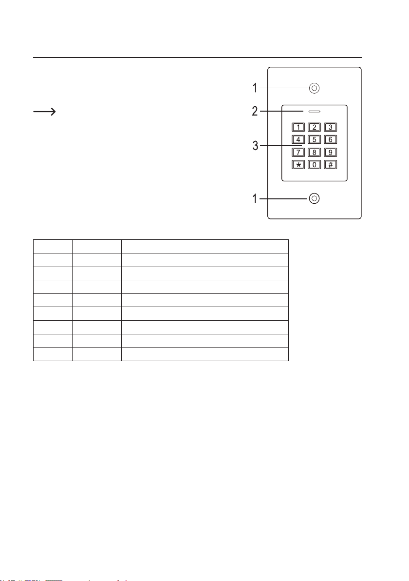
6. Controls and connections ....................................................................................................................................7
7. Installation and connection ..................................................................................................................................8
a) Installation .....................................................................................................................................................8
b) Connecting to conventional voltage/power supply ........................................................................................9
c) Connecting to alarm system..........................................................................................................................9
d) Wiegand interface........................................................................................................................................10
8. Operation........................................................................................................................................................... 11
9. Programming .....................................................................................................................................................12
a) Enabling/disabling programming mode .......................................................................................................13
b) Changing the master code ..........................................................................................................................13
c) Pairing user transponders ...........................................................................................................................14
d) Deleting the user transponder .....................................................................................................................16
e) Saving a user code......................................................................................................................................17
f) Deleting the user code.................................................................................................................................19
g) Clearing all memory cells ............................................................................................................................19
h) Selecting the access mode..........................................................................................................................20
i) Saving a user PIN........................................................................................................................................21
j) Changing a user PIN ...................................................................................................................................22
k) Setting the changeover contact activation time...........................................................................................23
l) Enabling or disabling protection against incorrect entries ...........................................................................24
m) Setting the alarm time for protection function..............................................................................................24
n) visitor transponder or visitor code................................................................................................................25
o) Resetting all settings to factory defaults; pairing a new master transponder ..............................................27

3
Page
10. Operation...........................................................................................................................................................29
a) Getting started.............................................................................................................................................29
b) Accessing via valid user transponder..........................................................................................................30
c) Accessing via valid user code .....................................................................................................................30
d) Access via valid user transponder and user PIN.........................................................................................30
e) Accessing via door opener button ...............................................................................................................30
11. Troubleshooting .................................................................................................................................................31
12. Cleaning and maintenance................................................................................................................................33
13. Disposal.............................................................................................................................................................33
14. Declaration of Conformity (DOC).......................................................................................................................33
15. Technical data....................................................................................................................................................34

4
1. Introduction
Dear customer,
Thank you for purchasing this product.
This product complies with statutory, national and European regulations.
To ensure that the product remains in this state and to guarantee safe operation, always follow the instructions in this
manual.
These operating instructions are part of this product. They contain important information on setting up and
using the product. Do not give this product to a third party without the operating instructions. Therefore,
retain these operating instructions for reference!
All company and product names contained herein are trademarks of their respective owners. All rights reserved.
If there are any technical questions, please contact: www.conrad.com/contact
2. Explanation of symbols
The symbol with the lightning in the triangle is used if there is a risk to your health, e.g., due to an electric
shock.
The symbol with an exclamation mark in a triangle is used to highlight important information in these oper-
ating instructions. Always read this information carefully.
The arrow symbol indicates special information and tips on how to use the product.

5
3. Intended use
This product is designed to prevent unauthorised access to doors (e.g. in an ofce) and to activate/disable alarm
systems. The product enables to save up to 1000 users with different transponders and user codes.
A valid access attempt activates a potential-free relay changeover contact (see contact rating under “Technical data”).
In this case, for example, a door opener or an alarm system can be triggered.
The product is intended for vertical installation on a wall and is suitable for indoor and outdoor use (IP 66).
For safety and approval purposes, do not rebuild and/or modify this product. Using the product for purposes other than
those described above may damage the product. In addition, improper use can cause hazards such as a short circuit,
re or electric shock. Read the operating instructions carefully and store them in a safe place. Only make this product
available to third parties together with its operating instructions.
This product complies with statutory, national and European regulations. All company and product names contained
herein are trademarks of their respective owners. All rights reserved.
4. Delivery content
• Code lock
• Fasteners (2x special screws with matching L key, 4x screw head stickers, mounting frame with 4x screws and 4x
dowels)
• Master transponder
• 1N4004 diode (for relay changeover contact)
• Quick start
• Programming guide
Up-to-date operating instructions
Download the latest operating instructions at www.conrad.com/downloads or scan the QR code
shown. Follow the instructions on the website.

6
5. Safety information
Damage caused due to failure to observe these instructions will void the warranty. We shall not be
liable for any consequential damage!
We shall not be liable for damage to property or personal injury caused by incorrect handling or
failure to observe the safety information! Such cases will void the warranty/guarantee.
• This product is not a toy. Keep it out of the reach of children and pets.
• Protect the product from extreme temperatures, impacts, ammable gases, vapours and solvents. The
code lock is suitable for indoor and outdoor installation and use (IP66).
• Handle the product carefully. Jolts, impacts or a fall even from a low height may damage the product. Do
not place the product under any mechanical stress.
• Do not mount or connect the product when it is connected to a power supply.
• The contact rating for the changeover contact is specied in section “Technical data” and must not be
exceeded. Never switch the mains voltage, as this can cause life-threatening electric shock!
• Always observe safety information and operating instructions for the other devices (e.g. door opener,
alarm system) to which the product is connected.
• If it is no longer possible to operate the product safely, stop using it and prevent unauthorised use. Safe
operation of the appliance can no longer be guaranteed if it shows visible signs of damage, malfunctions,
has been exposed to unfavourable storage conditions or signicant transport loads.
• For installations in industrial facilities, follow the accident prevention regulations for electrical systems
and equipment issued by the national safety organisation or the corresponding national authority.
• Do not leave packaging material lying around carelessly. It may become a dangerous toy for children!
• Maintenance, modications and repairs must be carried out by a technician or a specialist repair centre.
• If you are not sure how to operate the product correctly, or if you have any questions that are not an-
swered in these operating instructions, contact us or another specialist.

7
6. Controls and connections
1 Opening for wall mounting
2 LED indicator
3 Keypad with an integrated RFID sensor behind it
There is a brightness sensor on the rear, which serves as tamper
protection.
Connecting cable:
Colour Inscription Function
Red 12 - 18 V/DC Power supply 12 - 18 V/DC
Black GND GND/ground
Blue NO NO (normally open) contact of relay
Brown COM COM (centre contact) contact of relay
Grey NC NC (normally closed) contact of relay
Yellow OPEN Door opener button
White D1 Wiegand Data1
Green D0 Wiegand Data0

8
7. Installation and connection
Ensure that the connection cables are not kinked or squashed. This can cause malfunctions, short circuits
and device defects. Ensure that no cables or wires are damaged when drilling holes or tightening screws.
Installation and connection may only be carried out when power supply is switched off.
Make sure that the brightness sensor on the back is not exposed to light beams after installation, as switch-
ing on the system could cause activation of tamper protection with subsequent locking of all functions.
a) Installation
Use suitable screws and, if necessary, dow-
els to mount the mounting plate with the
module on the wall (see gure on the right)
depending on the type of wall.
The package includes two special screws
and a matching L-key. The screw head
shape provides extra protection against at-
tempted manipulations.
The included mounting frame can be pre-in-
stalled depending on the surface and instal-
lation position, and the code lock should then
be screwed tight.
Depending on the surface, use suitable
screws and, if necessary, dowels.
A hole for the connecting cable must be drilled before fastening. Wiring should be carried out according to the wiring
diagrams in the following sections.
Ensure that there is suitable insulation (e.g. heat shrink tubing).
A protective diode is included for connecting a door opener. It protects the electronics from damage caused by volt-
age surges. Ensure the correct polarity, as shown in the following wiring diagrams (when connected, the ring on the
protective diode must face the positive pole/+).
Caution!
Never switch the mains voltage via the potential-free changeover contact! There is a risk of fatal electric
shock! Observe the permissible contact rating; see “Technical data” chapter.
Use suitable cables with different colours. Note the colours and store this information together with these
instructions. When connecting the cables, pay attention to the correct polarity (plus/+ and minus/-).
You can use the included stickers to cover the screw openings after cable connection and successful start-up.

9
b) Connecting to conventional voltage/power supply
When a conventional power supply unit should be used, observe the following gures with the wiring diagram.
A) “Fail-secure” door opener: Releases the locking latch only when its operating voltage is applied (common design
for front doors).
B) “Fail-safe” door opener: releases the locking latch only when the operating voltage is missing (uncommon design,
e.g. used for escape route doors, which can be opened in the event of a power outage).
The included diode must be connected correctly near the door opener to protect the code lock from voltage
surges.
1 Code lock
2 Door opener button
3 Power adapter
4 “Fail-Secure” door opener
5 “Fail-Safe” door opener
c) Connecting to alarm system
Observe the operating instructions for the alarm system used. The code lock relay switches when a valid transponder
is recognised. An alarm system can thus be enabled or disabled.
1
2
3
4
5
1
2
3

10
d) Wiegand interface
There are two application options for the Wiegand interface of the code lock:
1) The code lock is used as an external card reader
The code lock can be connected to a compatible
Wiegand controller and used as an external card reader.
The Wiegand controller must support a 26-bit protocol
that is used for the transmission of transponder data.
Follow the operating instructions for your
Wiegand controller.
1 Code lock
2 Wiegand controller
3 Power adapter
The code lock has the operating voltage of 12 - 18 V/DC. If the Wiegand controller does not support this
operating voltage, the code lock will require a separate power supply unit. The wiring diagram will then be
different from the one shown in the gure.
2) An external card reader is connected to the code lock
The code lock functions as a Wiegand controller and can be operated with an external card reader (with 26- or 34-bit
protocol, automatic recognition).
Card readers for 125 kHz transponders as well as card readers with MIFARE®chip card technology
(13.561 MHz) are supported.
When a MIFARE®smart card reader is used, new transponders can only be paired via this card reader.
However, when a card reader for 125 kHz transponders is used, transponders can be paired both via the
code lock and the card reader (should you face any problems, use only the external card reader for pairing).
Ensure that the two data lines D0 and D1 are not swapped; D0 must always be connected to D0 and D1 to D1. Other
connections can be carried out as shown in section 7. b). Always follow the operating instructions for the external
card reader.
1
2
3
Autres manuels pour 2380478
1
Table des matières
Autres manuels Sygonix Verrouillage

Sygonix
Sygonix UP IP66 Manuel utilisateur

Sygonix
Sygonix LKBK-2209 Manuel utilisateur

Sygonix
Sygonix 43172W Manuel utilisateur

Sygonix
Sygonix Touch S Manuel utilisateur

Sygonix
Sygonix SY-4730012 Manuel utilisateur

Sygonix
Sygonix 2522226 Manuel utilisateur

Sygonix
Sygonix 1559246 Manuel utilisateur

Sygonix
Sygonix 2250408 Manuel utilisateur

Sygonix
Sygonix 1717531 Manuel utilisateur


