SVC GROUP WEDI-4 Manuel utilisateur

Wireless External Data
Interface (WEDI-4)
P/N: ASM1024-600
SER MAN AL
Revision 1.0
29 Firemens Way, Poughkeepsie, New York 12603 SA
Voice: (845) 471-7007, Fax: (845) 471-7020, E-mail: [email protected]
Copyright
2019 Spectra Vista Corporation


SVC WIRELESS EXTERNAL DATA INTERFACE 4 CHANNEL USER MANUAL REVISION 1.0
Table Of Contents
INTROD CTION .................................................................................................................................. 1
FOR BEST RESULTS, THE WEDI-4 MAY BE MOUNTED ON A TRIPOD USING ITS BUILT-IN ¼-20
BOTTOM MOUNT, AS SHOWN BELOW............................................................................................... 3
CONTROLS AND INDICATORS ........................................................................................................ 4
P
OWER
S
WITCH
.................................................................................................................................................................... 4
LED/A
UDIO
B
EEPER
......................................................................................................................................................... 4
PAIRING WEDI-4 WITH YO R INSTR MENT .............................................................................. 5
WEDI-4 SAGE – STAND-ALONE MODE ........................................................................................ 7
WEDI-4 SAGE – PC MODE................................................................................................................ 9
WEDI-4 RECHARGEABLE BATTERY .............................................................................................. 12
C
HARGING
T
HE
B
ATTERY
............................................................................................................................................... 12
C
HECKING
B
ATTERY
OLTAGE
..................................................................................................................................... 13
R
EPLACING THE
B
ATTERY
............................................................................................................................................... 15
CONFIG RATION OPTIONS ........................................................................................................... 18
SPECIFICATIONS ............................................................................................................................... 19
APPENDIX A – HARDWARE DESCRIPTION ..................................................................................20

SVC WIRELESS EXTERNAL DATA INTERFACE 4 CHANNEL USER MANUAL REVISION 1.0
Table Of Figures
Figure 1 WEDI-4 Top iew Showing Built-In PAR Sensor ........................................................................................... 1
Figure 2 WEDI-4 Side iew Showing External Sensor Inputs – Pyranometer (SPN-1), and Thermistor (T) ....... 1
Figure 3 Using The WEDI-4 In The Field With arious Sensors .................................................................................. 2
Figure 4 i-Series External Data Bluetooth Antenna Location ......................................................................................... 3
Figure 5 WEDI-4 Mounted Securely To A Tripod ........................................................................................................... 3
Figure 6 WEDI-4 Power Switch ........................................................................................................................................... 4
Figure 7 WEDI-4 Unique Bluetooth Address Tag, Chassis Bottom .............................................................................. 5
Figure 8 PC Software Pairing ................................................................................................................................................. 5
Figure 9 LCD Pairing Process, Before Turning On The WEDI-4 ................................................................................. 6
Figure 10 LCD Pairing Process, Completed ....................................................................................................................... 6
Figure 11 Waiting for the Initial Reference Scan ............................................................................................................... 7
Figure 12 LCD Indicating Downwelling Radiance Is Currently Down 3 Percent vs Reference ............................... 8
Figure 13 LCD Indicating Downwelling Radiance Is Currently Up 10 Percent vs Reference .................................. 8
Figure 14 PC Software WEDI Controls Example ............................................................................................................. 9
Figure 15 PC Software New Main Screen Buttons and External Data Display Fields ............................................. 10
Figure 16 External Data Display After Reference Scan .................................................................................................. 11
Figure 17 External Data Display After Ext Data Scan ................................................................................................... 11
Figure 18 External Data Display After Target Scan - Cloud Cover! ............................................................................ 11
Figure 19 WEDI-4 Battery Charging Port ........................................................................................................................ 12
Figure 20 WEDI-4 Battery Charger ................................................................................................................................... 12
Figure 21 WEDI-4 Battery oltage Displayed On Channel 5 ....................................................................................... 13
Figure 22 Battery oltage Measurement - Across SPN-1 Connector Pins 2 and 3 ................................................... 14
Figure 23 Battery Replacement – Opening The Unit ...................................................................................................... 15
Figure 24 Battery Replacement - Connector J2 "BATT" Partially Removed ............................................................. 16
Figure 25 Battery Replacement - Old Battery Prepared For Removal ......................................................................... 16
Figure 26 WEDI-4 Battery With Foam Tape Applied .................................................................................................... 17

1
11
1
SVC WIRELESS EXTERNAL DATA INTERFACE 4 CHANNEL USER MANUAL REVISION 1.0
Introduction
The S C 4 channel Wireless External Data Interface (WEDI-4) is a companion product to the
Spectra ista i-Series of spectroradiometers. The WEDI-4 provides a platform to wirelessly inject
data from the built-in Li-Cor PAR sensor, as well as data from external sensors, into the scan data
acquired by the spectroradiometer.
Figure 1 WEDI-4 Top iew Showing Built-In PAR Sensor
Figure 2 WEDI-4 Side iew Showing External Sensor Inputs – Pyranometer (SPN-1), and Thermistor (T)
The WEDI-4 provides a cost effective method to monitor and record data from sensors, while
acquiring high-quality spectral data with the S C i-Series spectroradiometers. The i-Series

2
22
2
SVC WIRELESS EXTERNAL DATA INTERFACE 4 CHANNEL USER MANUAL REVISION 1.0
spectroradiometers incorporate a second Bluetooth radio, which can receive data from sensors
connected to the WEDI-4.
The external sensors and WEDI-4 can be placed near the area of interest as the spectroradiometer is
moved from target to target. By using just the PAR Sensor (supplied with the WEDI-4) the
instrument operator can be alerted to changes in downwelling irradiance and take action to avoid
collecting erroneous data. The i-Series instruments record the external sensor data for each
measurement.
The i-Series spectroradiometer operator is immediately aware of changes to downwelling sensor
signal, and can take the appropriate action.
Figure 3 Using The WEDI-4 In The Field With arious Sensors
Note that the antenna located on the upper right side of i-Series rear panel is the one used to
communicate with the WEDI-4. When not in use, it is recommended that the External Data
Bluetooth Antenna be removed and replaced with the cap furnished with the instrument.

3
33
3
SVC WIRELESS EXTERNAL DATA INTERFACE 4 CHANNEL USER MANUAL REVISION 1.0
Figure 4 i-Series External Data Bluetooth Antenna Location
For best results, the WEDI-4 may be mounted on a tripod using its built-in ¼-20 bottom mount, as
shown below.
Figure 5 WEDI-4 Mounted Securely To A Tripod
4
44
4
SVC WIRELESS EXTERNAL DATA INTERFACE 4 CHANNEL USER MANUAL REVISION 1.0
Controls And Indicators
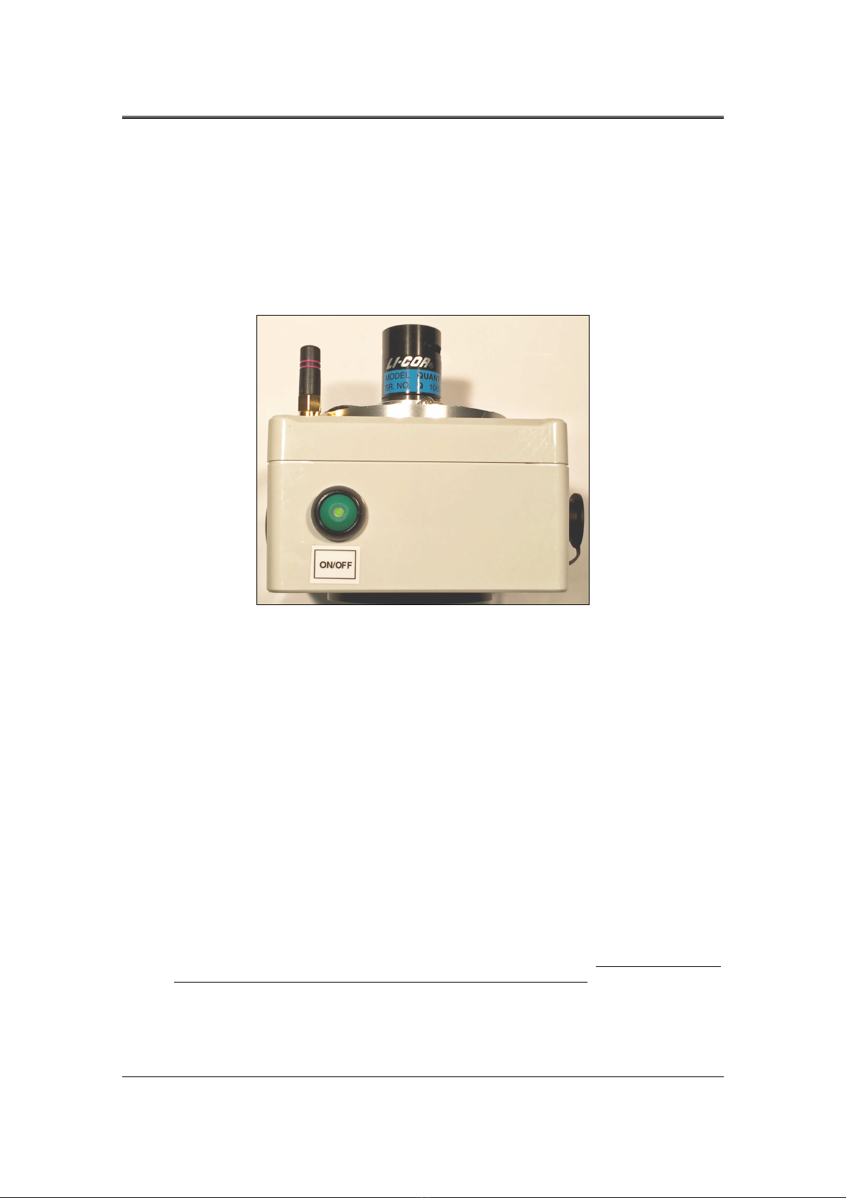
Power Switch
The power switch is of type push-on / push-off, with an LED indicator mounted in the center of the
round power switch push button.
Firmly press the power switch once to turn power on, and press again to turn power off.
Figure 6 WEDI-4 Power Switch
LED/Audio Beeper
The WEDI-4 uses an internal audio beeper and power switch mounted LED to indicate the following
conditions:
At power-up:
The unit emits a single 1 second beep to indicate that power has been applied, and that the firmware
has successfully started. The LED lights and stays on solid to indicate sufficient battery voltage to run
the device.
When the Bluetooth radio connection with the paired i-Series instrument has failed:
The unit emits a 1 second beep every 10 seconds until the connection to the instrument has been
restored.
When the battery voltage is low:
The unit emits a 0.5 second beep every 2 seconds, and flashes the power switch LED. When this
occurs, the WEDI-4 should be turned off until it the battery can be recharged. Failure to turn off the
unit under low-battery conditions will reduce the lifetime of the battery.

5
55
5
SVC WIRELESS EXTERNAL DATA INTERFACE 4 CHANNEL USER MANUAL REVISION 1.0
Pairing WEDI-4 With Your Instrument
The WEDI-4 uses a Bluetooth radio to wirelessly send sensor data to the i-Series instrument. Prior to
using the WEDI-4, this Bluetooth radio must be paired with a specific i-Series instrument. This
pairing process only needs to be performed once, as the i-Series instrument remembers the paired
device across power cycles.
Each WEDI-4 has a unique 12 character hexadecimal Bluetooth address. This unique address appears
on a tag located on the bottom of each WEDI-4 chassis, as shown below:
Figure 7 WEDI-4 Unique Bluetooth Address Tag, Chassis Bottom
The pairing process uses the i-Series PC Data Acquisition Software to configure the WEDI-4
Bluetooth address into the i-Series instrument.
Once the PC Data Acquisition Software is started and connected to the i-Series instrument, use the
software’s “Control->Setup External Data…” dialog to begin the pairing process (shown below).
Set the “External Data Source” field and “Bluetooth Address” field according to your model
instrument and your unique WEDI-4 Bluetooth address, and press the “Update Instrument” button
to send the address to the instrument.
Figure 8 PC Software Pairing
Over on the i-Series instrument LCD (setup screen #4, EXTERN DATA), the Bluetooth Address
should now match the one just sent from the PC software. See below:

6
66
6
SVC WIRELESS EXTERNAL DATA INTERFACE 4 CHANNEL USER MANUAL REVISION 1.0
Figure 9 LCD Pairing Process, Before Turning On The WEDI-4
To complete the pairing process:
•Press the “EXTERN DATA:” button on the LCD to changes its state to “ON”.
•Press the power switch on the WEDI-4 to turn the unit ON.
Once turned on and connected, the instrument’s LCD screen should change its “STATUS:” field to
“CONNECTED, DATA OK” as shown below: This indicates a successful pairing, with data
streaming from the WEDI-4 to the i-Series instrument.
Figure 10 LCD Pairing Process, Completed
Once the pairing is complete, press the “SA E SETTINGS” button. This will cause the i-Series
instrument to automatically attempt to re-connect to the WEDI-4 every time the instrument is
powered up. It will also automatically select channel 1 as the current display channel.
If the LCD shows any other STATUS after the above steps, then check:
•That the Bluetooth Address as found on the bottom of the WEDI-4 chassis was entered
correctly.
•Check/charge the WEDI-4 battery; it may be low.
•Ensure that the External Data BT Antenna, located to the right of the instrument’s LCD
display, has been installed.
Ce manuel convient aux modèles suivants
1
Table des matières
Autres manuels SVC GROUP Automobile électronique


