Sunwa SC-5 Manuel utilisateur

STAIR CHAIR
SC-5
OPERATION
MANUAL
POWERED
STAIR CLIMBER
SUNWA LTD.
Doc. No.
F-31-1

1
INTRODUCTION
Thank you for purchasing STAIR CHAIR, SUNWA POWERED SYAIR CLIMBER.
This manual describes proper operation procedure, inspection and maintenance.
Before running the machine, be sure to read this manual thoroughly.
Please keep this manual in the same, easily accessible place.
All machines are referred to by their serial numbers. Whenever you inquire about a machine, be sure to
inform us of its serial number.
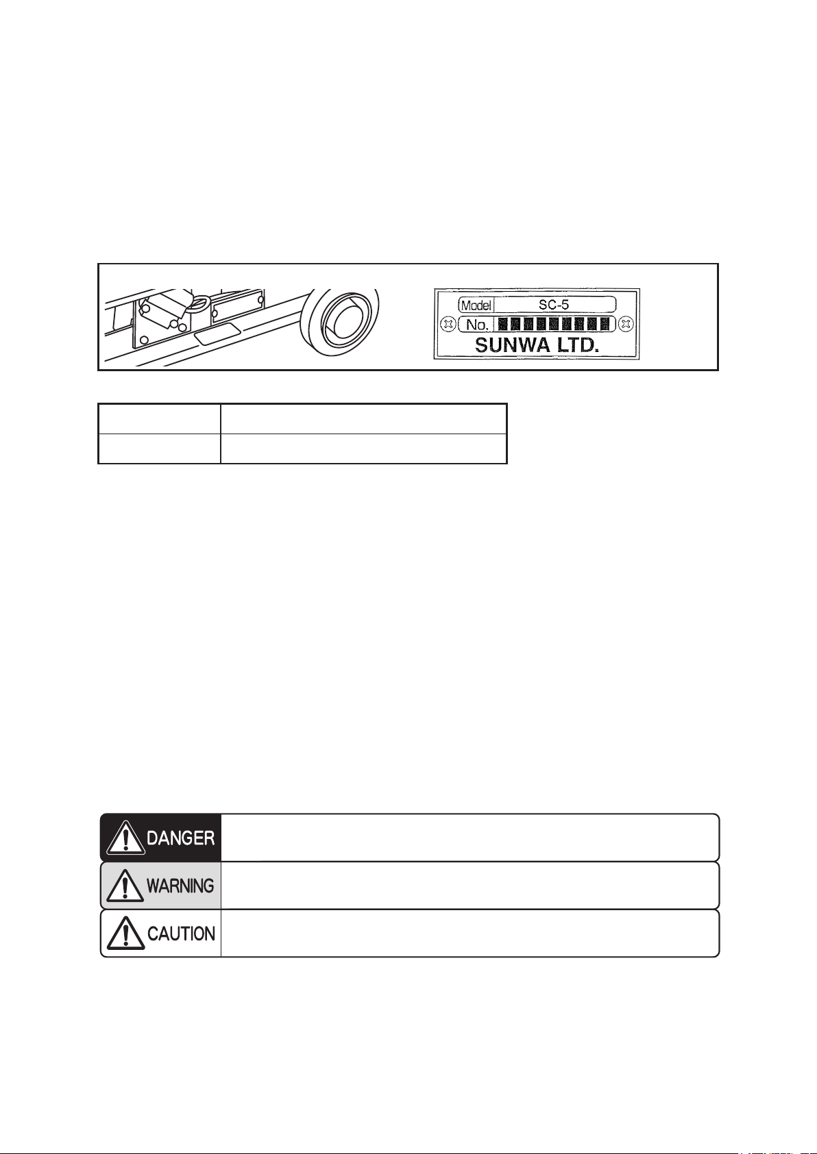
The serial number is inscribed on the name plate attached to the machine. Write it into the instruction
manual together with the date of entry.
Please write the serial number and date purchased in the following blank space.
Serial number
Purchased date Year Month Date
zWhen you inquire about the machine, please inform us of its serial number and purchase date.
zThis machine shall be operated only by an operator who has undergone the appropriate training program.
zSTAIR CHAIR SC-5 is for one passenger. Even if the total weight does not exceed the maximum
allowable load, a passenger holding a child on his/her lap will not be allowed because this is highly
dangerous. Be sure that only a single person mounts the machine, with the safety belt fastened.
zThe operator shall address the passenger upon each operation in order so that the passenger can be seated
without anxiety. (Especially during ascent/descent on a stairway, take special care so that passengers do
not have to feel anxiety.)
If any of the following events arise, be sure to notify your sales agent.
zWhen this machine is moved to another facility or transferred; or
zWhen necessity arises such that an uneducated operator has to operate the machine.
SAFETY PRECAUTIONS
To maintain safe operation, important safety precautions, classified into Danger, Warning and Caution, are
indicated in corresponding parts of the operation manual. The definition of each precaution is explained in
the following section.
zType, Serial number zPowered stair climber, STAIR CHAIR SC-5
- If you transfer this machine, be sure to attach this instruction manual to the machine. -
Neglecting this warning indication or operating the machine improperly may
cause serious personal injury or even death.
Neglecting this warning indication or operating the machine improperly may
seriously endanger the concerned person’s health or life.
Neglecting this warning indication or operating the machine improperly may
cause injury to the concerned person or damage the machine or related items.

34
11
.
11
.
AFTER-PURCHASE SERVICING
●Warranty and repair
The term of the warranty is one year from the purchase date.
Even during this period, in the following cases, repair expenses have to be paid.
a. Malfunction or damage due to erroneous usage or improper repair or alteration
b. Malfunction resulting from fire, earthquake, flood, lightning, or other natural disasters or
environmental pollution
c. Malfunction due to the usage of the battery, oil, battery charger, etc., other than specified
d. Consumables such as Batteries, Rubber Crawlers (traveling belts), Traveling Wheels, oil, etc.
e. Usage in foreign countries
As for repair after the expiration of the warranty term, please consult your sales agent. As far as repair is
possible, we will perform repairs upon your request and at your expense.
●Retention period of parts for repair
We retain the parts necessary for the maintenance of the product for at least seven years after the
termination of the production of the product.
For any unclear matters concerning the product or after-purchase servicing, please ask your sales agent.
●In case you wish to scrap this product
Please contact your sales agent or SUNWA LTD.

2012.7
SUNWA LTD.
571 Negishi. Sayama. Saitama 350-1325. Japan
Phone: +81-4-2954-6611
Fax: +81-4-2954-6617
URL: http://www.sunwa-jp.co.jp

2
TABLE OF CONTENTS
1. ESSENTIALS OF SAFE OPERATION
1-2
2. CONFIGURATION AND SPECIFICATIONS
3
2-1 PRODUCT CONFIGURATION .................................................................
3
2-2 SPECIFICATIONS ....................................................................................
3
3. NAME OF EACH UNIT
4
4. DESCRIPTION OF EACH UNIT
5-12
4-1 HOW TO SET THE BACK SUPPORT FRAME.........................................
5
4-2 HOW TO FOLD THE BACK SUPPORT FRAME ......................................
6
4-3 SWICHES .................................................................................................
7
4-4 KICK STAND.............................................................................................
8
4-5 HOW TO RESET THE CIRCUIT BREAKER.............................................
8
4-6 BATTERY PACK REMOVAL / INSTALLATION..........................................
9
4-7 BATTERY GAUGE INDICATION.............................................................
10
4-8 HOW TO USE THE STAIR GAUGE ........................................................
11
5. BATTERY CHARGE SYSTEM
13-18
5-1 BATTERY................................................................................................
13
5-2 CHARGER..............................................................................................
13
5-3 CHARGING PROCEDURE.....................................................................
14
5-4 MALFUNCTION, INSPECTION, RESOLUTION PROCEDURE.............
16
5-5 BATTERY REPLACEMENT ....................................................................
17
5-6 HANDLING WARNINGS OF LEAD BATTERY .......................................
18
6. PRE-USE INSPECTION
19-20
7. OPERATION
21-28
7-1 SEAT THE PASSENGER IN STAIR CHAIR ............................................
21
7-2 ASCENDING STAIRS.............................................................................
22
7-3 SWIVEL AT LANDING AREA .................................................................
25
7-4 DESCENDING STAIRS ..........................................................................
26
7-5 DISMOUNTING ......................................................................................
28
8. DAILY MAINTENANCE AND CARE
29
8-1 BATTERY................................................................................................
29
8-2 RUBBER CRAWLERS............................................................................
29
8-3 MACHINE STORAGE .............................................................................
29
9. PERIODIC VOLUNTARY INSPECTIONS
30
10. TROUBLESHOOTING
31
11. AFTER-PURCHASE SERVICING
32

3
1
.
<Staircase with curve>
<Staircase angle exceeding 35 degrees>
* See P12.
35 degrees
or over
<Spiral staircase>
(Stairs with a large rise or pitch)
Over 340 mm Over 180 mm
* See P1112.
(Icy stairs or damaged stairs)<Stairs with rough edges>
* See P12.
(Stairs with too round of an edge)
Acceptable condition of operator for rental business in nursing care insurance
Age : Basically the age shall be between 16 and 70 years old.
Disease : No history of episodic disease.
Height : Not less than 150 cm in height as a general rule.
Weight : As a general rule, weight shall be 45 kg or over.
Equilibrium sense
: Capable of climbing stairs backward.
Four limbs : No physical disability in both legs and arms.
Auditory and visual senses : No specific problem in auditory and visual senses.
1,900 mm or over
950 mm or over
900 mm or over
1
.
ESSENTIALS OF SAFE OPERATION
Before using STAIR CHAIR
zThis machine cannot be used on stairs as shown below.
Operating environment
Shape of stairs :
Neither spiral nor bent stairs
Slope of stairs : Not steeper than 36 degrees
Width of stairs : 900 mm or over
Width of landing
: 1,900 mm or over
Depth of landing
: 950 mm or over
Nose distance (pitch)
: 340 mm or under
Rise : 180 mm or under
Radius of nose (R)
:
R 9 mm or under
● Ensure that there are no loose non-slip
rubber mats on the stairs.

4
1Be sure to carry out inspection before usage.
zThe operator of STAIR CHAIR shall carry out inspection prior to
usage.
The initial inspection is necessary for safe operation.
2Handling of Battery
zBattery is a sealed type. It is unnecessary to refill it with water. Never
dismantle Battery.
zNever position Battery near a flame or short-circuit Battery.
zIf Battery is cracked and its electrolytic solution contacts skin or
clothes, immediately rinse the contaminated area with plenty of clean
water.
If electrolytic solution splashes into the eye, rinse the eye with plenty of
clean water and and consult an ophthalmologist.
zUse special Battery Charger for charging Battery.
3Safe operation with proper knowledge
zSince persons who have not undergone training cannot operate this
machine, be sure to undergo a training program prior to operation.
zProper clothes, suitable to machine control, must be worn.
zBefore seating or unseating the passenger on/from STAIR CHAIR, be
sure to extend Kick Stand to secure STAIR CHAIR.
zAfter the passenger is seated on STAIR CHAIR, firmly secure the
passenger with Belt.
zWear normal shoes or sport-type shoes.
Never operate the machine while wearing no open heeled shoes such as
slippers, sandals or equivalents.
zNo operator overworked, sick, taking medicine, intoxicated, or
otherwise inhibited may operate STAIR CHAIR.
4Operation on a staircase
zDo not use this machine on stairs as shown in P3.
Do not operate this machine askew on stairs. Doing so may cause an
accident and is highly dangerous.
zWhenever running the machine upward, the operator must always pay
attention to the area behind him/herself.
zWhenever running the machine downward, the operator must always
pay attention to the front of the machine.
zNever let go of the machine unless unavoidable circumstances separate
the operator from the machine.
zDo not use this machine to convey baggage or other articles.
5Machine stoppage
zIf the machine gives trouble, malfunctions or is damaged, immediately
stop operating the machine.
Running it with a trouble cause existing can result in a serious accident.
zWhen you use this machine after a long period of non-use, please
request inspection to your sales agent.

5
2
.
2
.
CONFIGURATION AND SPECIFICATIONS
2-1 PRODUCT CONFIGURATION
STAIR CHAIR consists of the following assemblies.
• Frame and Chair Units Standard
accessories
• Battery charger (12 V) 1 unit
• Drive Unit • Operation manual 1 copy
• Wheels • Sheet Cover 1 sheet
• Kick Stand • Key Chain 1 piece
• Battery Pack
2-2 SPECIFICATIONS
Model SC-5
Passenger 1 (Max.130 kg)
Operator 1
Rubber Crawlers 2 Rubber Crawlers (Width: 51 mm, Ground contacting length: 682 mm,
Tread 241 mm)
Motor Type: permanent-magnet DC motor, 1pc.
Brake Spring loaded electromagnetic brake, 1 pc.
Stair ascent speed 20 steps (6.0 m) / min. (for passenger weight: 130 kg)
Stair descent speed 34 steps (10.2 m) / min. (for passenger weight: 130 kg)
Maximum stair angle 35˚
Running time (min)/charge Ascending: 600 steps/30 min. Descending: 1020 steps / 30 min.
(for passenger weight: 130 kg)
Battery Small lead battery with control valve (PXL12180) or (PE12V17)
Charger Power input: AC 115V/230V, 50/60Hz, 1.0A Max.
Power output: 12VDC, 3A
Weight 48 kg
1286 mm
498 mm (Folded)
929 mm 413 mm
1085 mm (Folded)
Dimensional drawing

6
3
.
3
.
NAME OF EACH UNIT
Headrest
Stair Gauge
Seat
Lock Release Pin
Back Support
Frame
Abdominal Belt
Lock Release Lever
Kick Stand
Frame
Idler Wheel
Wheels
Circuit Breaker
(Manual reset type)
Charging Receptacle
Relay Box
Rubber Crawler
Sprocket
Reduction Gear,
Motor
Side Frame
Key Switch
UP/DOWN SwitchEmergency Stop Switch
Battery Gauge
Short Plug
[Operation Box]
[Battery Pack]
Leg Belt
Chest Belt

7
4
.
Unlatched operation is very dangerous. Before operating
the machine, be sure to confirm that Lock Unit securely
supports Back Support Frame.
CAUTION
Never operate Lock Pin latch/release operation while the
passenger is on STAIR CHAIR. Doing so may cause injury
to the passenger.
Do not let children operate STAIR CHAIR. It will result in
danger.
4
.
DESCRIPTION OF EACH UNIT
4-1 HOW TO SET THE BACK SUPPORT FRAME
Push Lock Release Lever, which is located above
Operation Box, to the left. Hold Back Support
Frame and let the frame slide slightly backward and
upward.
Lock Release Lever
Click!
[Left side] [Right side]
Lock pin for Back
Support Frame
Lock Release Pin
Click!
Lock pin for Back
Support Frame
Lock Release Pin
When Back Support Frame has slid slightly,
disengage your finger from the lever and let Back
Support Frame slide further to extract the frame
backward.
Let the frame slide backward until the locking
mechanism emits a clicking sound.
When the lock pin for Back Support Frame has
been locked securely and the frame will not retreat,
the setup is complete.
NOTE: Make sure that the lock pin for Back Support
Frame is securely caught on both sides of the
frame.
WARNING
Table des matières
Manuels Aide à la mobilité populaires d'autres marques

Rhythm Healthcare
Rhythm Healthcare B3800F Manuel utilisateur

AMF-BRUNS
AMF-BRUNS PROTEKTOR Manuel utilisateur

Drive DeVilbiss Healthcare
Drive DeVilbiss Healthcare OTTER Manuel utilisateur

Rhythm Healthcare
Rhythm Healthcare C500U Manuel utilisateur

Lumex
Lumex RJ4200A Manuel utilisateur

Rebotec
Rebotec Jumbo Manuel utilisateur