
Sunny Boy SWR 2500U Guide de configuration

SB2500U-11:NE3801
Grid Tied String Inverter for Photovoltaic Systems
Issue 1.2
Installation and Operator’s Manual
Sunny Boy
SWR 2500U
http://www.wholesalesolar.com/inverters.html
http://www.wholesalesolar.com/inverters.html
Sunny Boy 2500U Installation and Operator’s Manual
SB2500U-11:NE - 2- SMA Regelsysteme GmbH
http://www.wholesalesolar.com/inverters.html
http://www.wholesalesolar.com/inverters.html
Sunny Boy 2500U Installation and Operator’s Manual
SB2500U-11:NE - 3- SMA Regelsysteme GmbH
IMPORTANT SAFETY INSTRUCTIONS
This manual contains important instructions that shall be followed during in-
stallation and maintenance of the Sunny Boy.
To reduce the risk of electrical shock, and to ensure the safe installation and
operation of the Sunny Boy, the following safety symbols have been placed
throughout this technical description to indicate dangerous conditions and im-
portant safety instructions.
WARNING: This indicates a fact or feature very important for the safety of
the user and / or which can cause a serious hardware defect if not applied
appropriately.
Use extreme caution when performing this task.
NOTE: This indicates a feature that is important either for optimal and
comfortable usage or optimal operation of the system.
Follow instructions closely.
EXAMPLE: This indicates an example.
SAVE THESE INSTRUCTIONS
http://www.wholesalesolar.com/inverters.html
http://www.wholesalesolar.com/inverters.html

Sunny Boy 2500U Installation and Operator’s Manual
SB2500U-11:NE - 4- SMA Regelsysteme GmbH
IMPORTANT SAFETY INSTRUCTIONS
• All electrical installations shall be done in accordance with the local and
national electrical codes ANSI/NFPA 70.
• The Sunny Boy contains no user serviceable parts. Please return the unit
to an SMA authorized Service Center (see page 56) for maintenance.
• Before installing or using the Sunny Boy, please read all instructions and
cautionary markings in the technical description and on the Sunny Boy
and the PV-array.
• Connecting the Sunny Boy to the electrical utility grid must only be done
after receiving prior approval from the utility company and performed only
by qualified personnel.
• Completely cover the surface of all PV-arrays with opaque (dark) material
before wiring them. PV arrays produce electrical energy when exposed to
light and could create a hazardous condition.
• On top of the device you can find the heat sink of the Sunny Boy with
potential temperatures of over 175°F (80 °C). To reduce the risk of burns,
do not touch.
SAVE THESE INSTRUCTIONS
http://www.wholesalesolar.com/inverters.html
http://www.wholesalesolar.com/inverters.html

Sunny Boy 2500U Installation and Operator’s Manual
SB2500U-11:NE - 5- SMA Regelsysteme GmbH
Table of Contents
1Introduction ...............................................................................................................6
2Installation.................................................................................................................7
2.1 What Must Be Done in Case of Transport Damages?......................................7
2.2 Placement of the Sunny Boy ............................................................................8
2.3 Electric Connection.........................................................................................12
2.3.1 Preparation of the electric connection........................................................14
2.3.2 Connection to Electrical Utility Grid............................................................16
3Commissioning........................................................................................................20
4Operation and Failure Indication LEDs ...................................................................24
4.1 Operation Indicator .........................................................................................27
4.2 Ground Fault Indicator....................................................................................30
4.3 Failure Indication ............................................................................................31
4.4 Opening and closing of the Sunny Boy...........................................................36
4.5 Upgrading or modification of the Sunny Boy interface....................................39
4.6 Measuring Channels and Messages...............................................................41
4.7 Measurement Precision..................................................................................43
5Troubleshooting ......................................................................................................44
6Warranty Regulations and Liability..........................................................................46
7Technical Data ........................................................................................................48
7.1.1 Minimum MPP-voltage of the PV panel......................................................49
8Appendix .................................................................................................................56
http://www.wholesalesolar.com/inverters.html
http://www.wholesalesolar.com/inverters.html
Sunny Boy 2500U Installation and Operator’s Manual
SB2500U-11:NE - 6- SMA Regelsysteme GmbH
1 Introduction
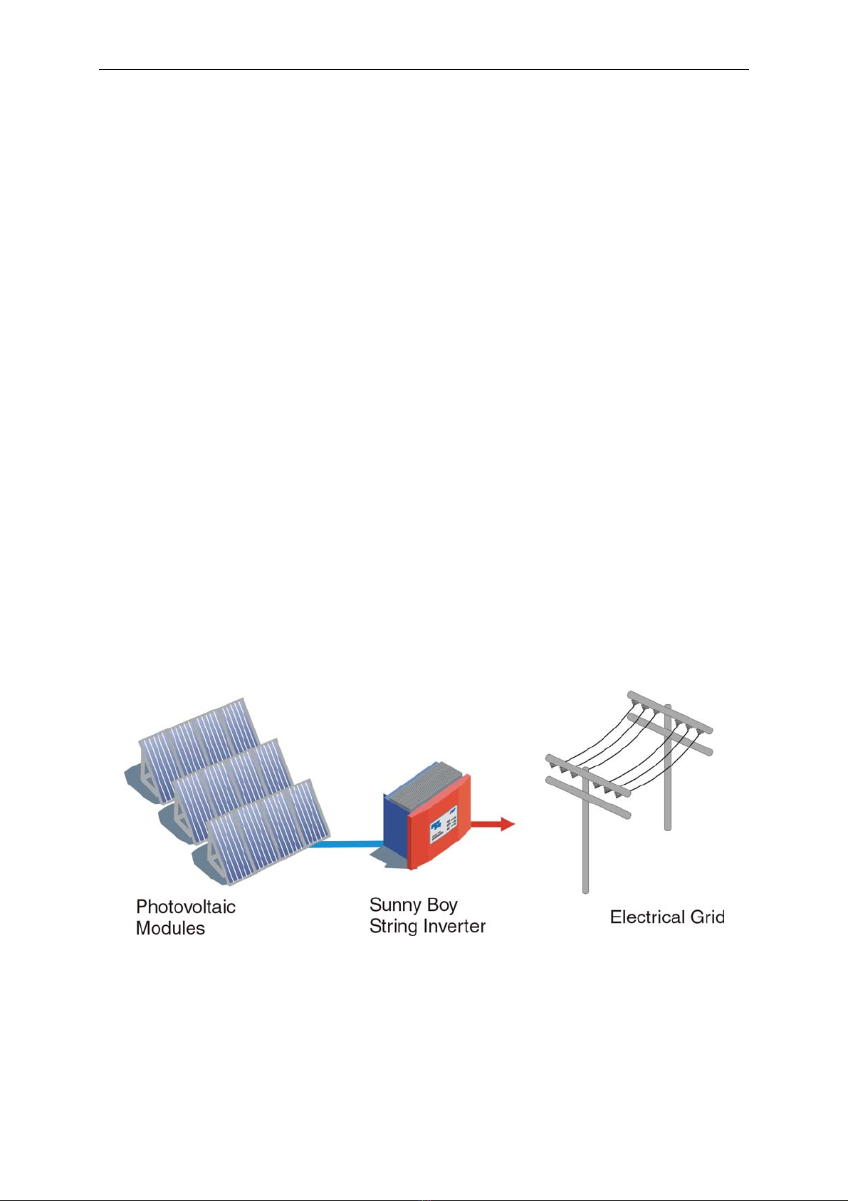
The SMA Sunny Boy is a string inverter for grid tied operation. With this manual the
Sunny Boy can be installed and operated in a safe way. This installer’s guide is used
as reference for the commissioning and as guideline on how to use all functions of
the inverter optimally and how you can extend your existing PV-plant.
Supplementary grid feeding includes the conversion of the DC-voltage from the PV-
panel to grid compatible AC-voltage with so-called ”inverters“ and the subsequent
connection to the electricity grid in the house distribution.
Here the electricity from the PV-modules provides all consumers with electric power
(household devices, lights etc.). In case that not enough power is produced the addi-
tionally necessary power is obtained from the grid. In case that there is a surplus of
power, this surplus is fed into the local grid and is therefore available for other con-
sumers. This way every single kilowatt-hour is utilized and the electricity company’s
power systems are relieved. In the most simple case a PV-plant therefore consists of
two basic components: the PV-panel and the inverter.
Fig. 1.1: Grid tied string inverter application
For a more detailed technical description of the Sunny Boy and its functionality
please read “Sunny Boy 2500U Technical Description”.
http://www.wholesalesolar.com/inverters.html
http://www.wholesalesolar.com/inverters.html
Sunny Boy 2500U Installation and Operator’s Manual
SB2500U-11:NE - 7- SMA Regelsysteme GmbH
2 Installation
WARNING: Before installing the Sunny Boy, read all instructions and cau-
tionary markings in the technical description and on the Sunny Boy and
the photovoltaic array.
WARNING: All electrical installations shall be done in accordance with all
local electrical codes and the National Electrical Code (NEC),
ANSI/NFPA 70.
WARNING: Connecting the Sunny Boy to the electrical utility grid must
only be done after receiving prior approval from the utility company and
performed only by qualified personnel.
2.1 What Must Be Done in Case of Transport Damages?
The Sunny Boy inverters are thoroughly checked before they are shipped. Even
though they are delivered in a sturdy packaging (which can be recycled) the inverters
can be damaged which is the forwarding company’s fault in most cases.
Please inspect your inverter thoroughly after it is delivered. If any damages can be
detected on the packaging that could lead to the conclusion that the contents is dam-
aged or if you detect that the inverter is damaged please immediately notify the for-
warding company.
SMA or your local supplier can help you in this matter. In any case the declaration of
transport damage must be made within 6 days upon receipt of the product and must
be stated in writing directly to the forwarding agent. If it is necessary to return the in-
verter to the manufacturer please use the packaging the inverter was sent in.
http://www.wholesalesolar.com/inverters.html
http://www.wholesalesolar.com/inverters.html

Sunny Boy 2500U Installation and Operator’s Manual
SB2500U-11:NE - 8- SMA Regelsysteme GmbH
2.2 Placement of the Sunny Boy
The Sunny Boy is a sophisticated electronic device and is therefore sensitive to hu-
midity within the case.
NOTE: If the Sunny Boy is placed outside, the humidity during the installa-
tion should be as low as possible - pay special attention that it does not
rain. If moisture is enclosed in the case it will eventually condense within
the device which could damage the electronics.
A suitable position must be found for the inverter while the PV-plant is designed. In
the following you will find a summary of the most important criteria.
Criteria for device mounting:
• Due to the high protection class (NEMA 4X) of the enclosure the installation is
possible indoors as well as outdoors.
• If possible, do not expose the inverter to rain despite NEMA 4X.
• Keep the DC-cabling from the solar panel to the inverter as short as possible.
• Avoid installation in the living area because a slight noise emission is possible.
• Avoid mounting on resonant parts (e. g. thin wooden panels, plaster panels,
etc.). The Sunny Boy tends to slightly vibrate when under load.
• Provide accessibility for installation and later service.
• Installation in eye-height allows to easily read the operating LEDs or the Sunny
Display.
http://www.wholesalesolar.com/inverters.html
http://www.wholesalesolar.com/inverters.html
Sunny Boy 2500U Installation and Operator’s Manual
SB2500U-11:NE - 9- SMA Regelsysteme GmbH
CAUTION: Please note the following points in any case:
• The mounting background must be firm.
• The ambient temperature must be between -13 °F and +140 °F.
• The National Electrical Code (NEC) requires that the inverter be
connected to a dedicated circuit and no other outlets or device may
be connected to this circuit. See NEC Section 690-64(b)(1). The
NEC also impose limitations on the size of the inverter and the man-
ner in with it is connected to the utility grid. See NEC Section 690-
64(b)(2).
• Do not expose the string inverter to direct sunlight (if necessary in-
stall a shading roof).
• A minimum distance of 8 inch (200 mm) must be clear above the in-
verter for ventilation, i. e. no cupboards, ceiling, etc.
• Free air circulation around the case must not be obstructed.
• If you are installing the Sunny Boy in a cabinet or closet etc., the ai
r
circulation must be sufficient for heat dissipation - provide external
ventilation.
• The heat sink can reach a temperature of more than 175 oF.
• Check existing electrical installations or plumbing prior to drilling
holes into the wall.
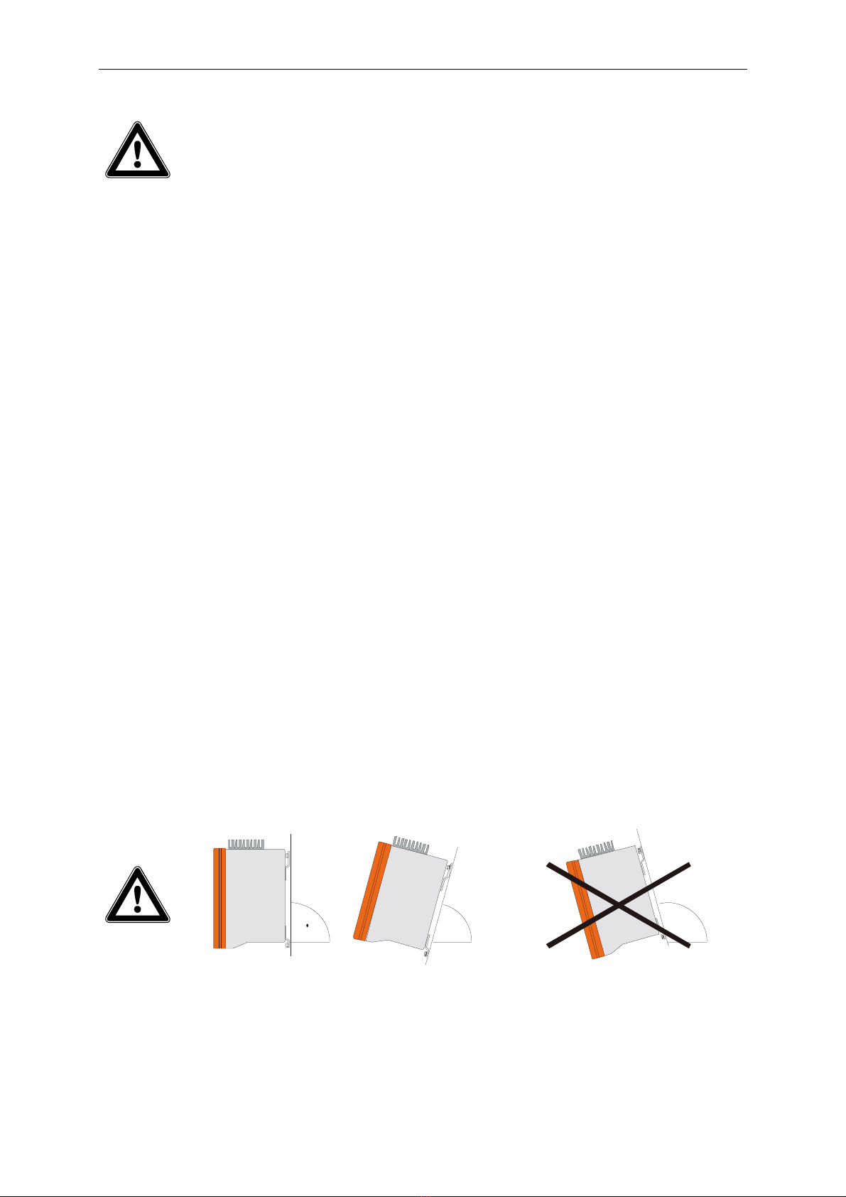
• Provide a correct position of the inverter - see below:
mount straight or tilted to the back never mount tilted to front
Fig. 2.1: How to mount the Sunny Boy
http://www.wholesalesolar.com/inverters.html
http://www.wholesalesolar.com/inverters.html
Sunny Boy 2500U Installation and Operator’s Manual
SB2500U-11:NE - 10 - SMA Regelsysteme GmbH
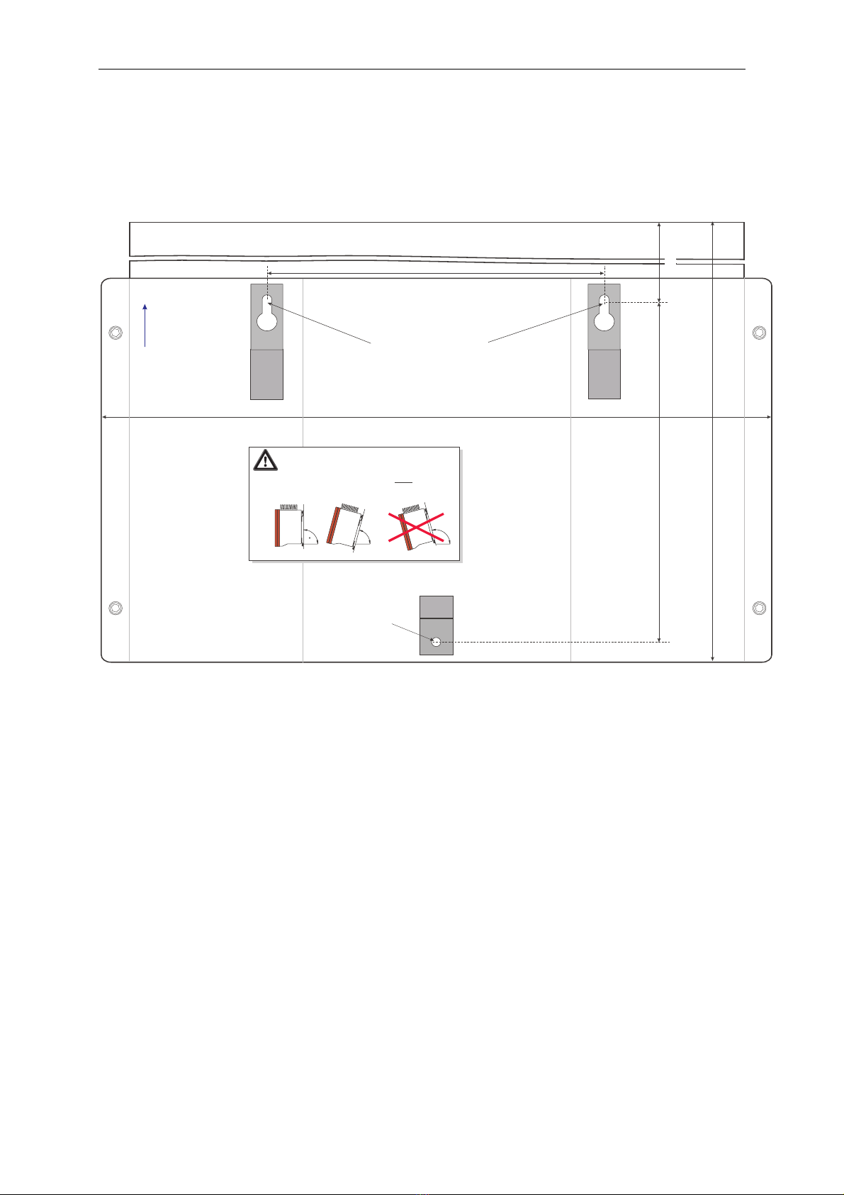
The Sunny Boy inverter is mounted on the back side with the three metal straps.
Total height of the Sunny Boy: 295.50 mm
=
=
Total width of the Sunny Boy: 434.50 mm
+
++
Drilling Template for the Sunny Boy 2000, 2500, 3000
63,50 mm
position of the holes on the top
(for 6 mm screws)
bottom hole
(6 mm diam.)
distance between the holes on the top 217.50 mm
top
Please note:
mount the Sunny Boy
tilted to the back or
vertical!
Never mount the
Sunny Boy tilted
to the front!
vertical distance between the holes: 220.50 mm
Fig. 2.2: Picture of drilling template - original template in appendix
http://www.wholesalesolar.com/inverters.html
http://www.wholesalesolar.com/inverters.html
Table des matières
Autres manuels Sunny Boy Onduleur


