Sundown Audio SDX 400.1 Manuel utilisateur

Mono Blocks:
SDX 400.1
SDX 800.1
SDX 1200.1
Multi - Channel
SDX 90.2
SDX 100.4
SDX 200.2
SDX 100.6
This manual is intended to be a guide, installation by a qualified professional is recommended

SDX SERIES AMPLIFIER OWNER’S MANUAL version 07/21 v2
Digital Class-D Mono Block Amplifier
Dual MOS-FET PWM Power Supply
1 Ohm Stable Load
12 dB/Octave - Variable Low Pass Filter
DC Auto sense feature
0 to 12dB - Variable Bass Boost
4 Way Protection Circuit (Thermal,
Voltage Speaker short and DC Offset)
Wired Remote Control
Tested @14.4Volts SDX 400.1 SDX 800.1 SDX 1200.1
1Ω Mono RMS 400W 800W 1200W
2Ω Mono RMS 300W 550W 825W
4Ω Mono RMS 175W 315W 450W
Recommended Fuse Rating 40A 80A 120A
LoW Pass Filter
(-12dB/8) Variable 50hz-250hz
Input Sensitivity 6V Max
Signal Noise Ratio 90dB 87dB 83dB
Working Voltage 11.5V - 15V
Width mm 102 178 178
Length mm 147 226 312
Height mm 54 54 54
Width inches 4 7 7
Length inches 5.75 8.875 12.25
Height inches 2.125 2.125 2.125
DIGITAL MONOBLOCK FEATURES
DIGITAL MONOBLOCK
SPECIFICATIONS

SDX SERIES AMPLIFIER OWNER’S MANUAL version 07/21 v2
High Efficiency Digital Multi-Channel
Design
12dB/Octave-Variable High Pass Filter
12dB/Octave-Variable Low Pass Filter
DC Auto sense feature
4 Way Protection Circuit (Thermal,
Voltage Speaker short and DC Offset)
Optional Wired Remote Control
Tested @14.4Volts SDX 90.2 SDX 100.4 SDX 200.2 SDX 100.6
4Ω RMS bridged 240W 270Wx2 560W 300Wx3
2Ω RMS 120Wx2 135Wx4 280Wx2 150Wx6
4Ω RMS 90Wx2 100Wx4 200Wx2 100Wx6
Recommended
Fuse Rating
25A 50A 50A 80A
Low Pass Filter
(-12dB/8) Variable
30hz -
500hz
ch3/4 30hz -
500hz or 600hz
- 10khz @20x
20hz - 500hz
(ch5/6 30hz - 500hz) (ch3/4
30hz - 500hz or 600hz - 10khz
@20x) (ch1/2 15hz - 500hz or
300hz - 10khz @20x)
High Pass Filter
(-12dB/8) Variable
15hz -
500hz
ch1/2 15hz -
500hz or 300hz
- 10khz @20x
ch3/4 15hz -
500hz
20hz - 500hz
ch1/2 15hz - 500hz or 300hz -
10khz @20x ch3/4 15hz -
500hz
Input Sensitivity 6V Max
Signal Noise Ratio 78dB
Working Voltage 11.5V - 15V
Width mm 105 178 178 178
Length mm 148 226 226 312
Height mm 54 54 54 54
Width inches 4.125 7 7 7
Length inches 5.825 8.875 8.875 12.25
Height inches 2.125 2.125 2.125 2.125
FULL RANGE
DIGITAL
SPECIFICATIONS
FULL RANGE DIGITAL
FEATURES

SDX SERIES AMPLIFIER OWNER’S MANUAL version 07/21 v2
Some features not available on all models
PWR/PRT led: Power LED, it will be blue if it’s on, and your good, if its off, you’re not good. See the
troubleshooting section if it doesn’t turn on. Protect, if the LED is red, then the amp is in protect mode, see the
troubleshooting section for assistance.
POWER (B+, REM, GND): Connection for power source, see the Power Connections page for details
CH1-CH6 SPEAKER OUTPUTS: This is where your speakers plug in, see the amp specific
diagrams for assistance.
AUTO SENSE: What signal are you using to turn on the amp.
SIG: Detect signal from the HI-LEVEL inputs.
OFF: Turns off auto sense when using the REM (remote) turn on option.
DC: Turn on with B+, usually used in installs where the battery/power is disconnected when not in use
REMOTE: Plugin for the external bass knob, used to attenuate the from lowest point to the highest that was
set on the amplifier
5/6 CH INPUT, 3/4 CH INPUT: Duplicates the signals from CH1 and CH2 to CH3/CH4 and
CH5/CH6. Press the button in to duplicate, do not use the inputs on CH3/CH4 or CH5/CH6 if using this
feature.
CH1-CH6 RCA’s: RCA signal from source
OUTPUT RCA: Passthrough output to a secondary amplifier
Hi-Level In: Input for high level signals, do not use RCA’s when using these inputs
WHAT DO ALL THE SWITCHS, KNOBS AND LIGHTS DO?

SDX SERIES AMPLIFIER OWNER’S MANUAL version 07/21 v2
LEVEL/GAIN: NOT A VOLUME KNOB, THE INTERNET IS LYING TO YOU
😊, used to set the input signal levels, start from Min and slowly turn clockwise
until you hear angels singing or the sirens from the cops looking for you. Scan this
QR Code for a video on setting your gains
FILTER: Turns the internal crossover on or off, you typically would not turn it off
unless you have an external processor or crossover. Turning these off without
external protection could damage your speakers
RANGE: Multiplier for the crossover point for the LPF and HPF knobs, x1 will indicate the top frequency
range, x20 will indicate the bottom range.
LPF: Low pass filter – Filters out high frequencies
HPF: High pass filter - Filters out low frequencies
SUBSONIC: Filters out low frequencies on the lower spectrum, this is used to protect subwoofers from
playing frequencies lower than they were designed to handle.
PHASE- Turn to adjust the phase. Can be used on 180 when inverting woofers.

SDX SERIES AMPLIFIER OWNER’S MANUAL version 07/21 v2
+12V Battery
You need to connect a power wire to the vehicle’s positive battery terminal. This connection must be tight and
secure to ensure proper connectivity. This wire has to be fused appropriately (see each amplifier’s fuse rating
under specifications) within 12 to 16 inches for safety. You will then need to connect the power wire to the B+
terminal of the amplifier with a Phillips screw driver. Do not install the fuses until installation is complete.
Ground Connection
It is recommended that you connect your ground directly to your power source ground for the best possible
performance. However, if you cannot, then the ground connection must be made to the vehicle’s chassis and
should be kept as short as possible, while accessing a solid piece of sheet metal in the vehicle. The surface
should be sanded at the contact point to clean rust, paint or grime so a metal-to-metal connection between the
chassis and the termination of the ground wire is effective. You will then need to connect the ground wire to the
GND terminal of the amplifier.
Remote
The +12V remote turn-on wire is typically controlled by the source unit’s remote turn-on output. The amplifier
will turn on when +12V is present at its remote (REM) input and turn off when +12V is switched off. Connect
the remote wire using 12 to 16-gauge wire to the REM connection of the amplifier, then connect the other end
of the remote wire to either the source unit’s turn on output or ignition switch circuit. The models that have the
extra power input will have an extra REM connection noted as OUT, this is intended to allow you to connect
your REM line to other devices if needed.
WARNING
The SDX Line of amplifiers do not come with external fusing.
Make sure you install appropriate in line fusing from the
positive side of your power source.
POWER CONNECTIONS
SDX SERIES AMPLIFIER OWNER’S MANUAL version 07/21 v2
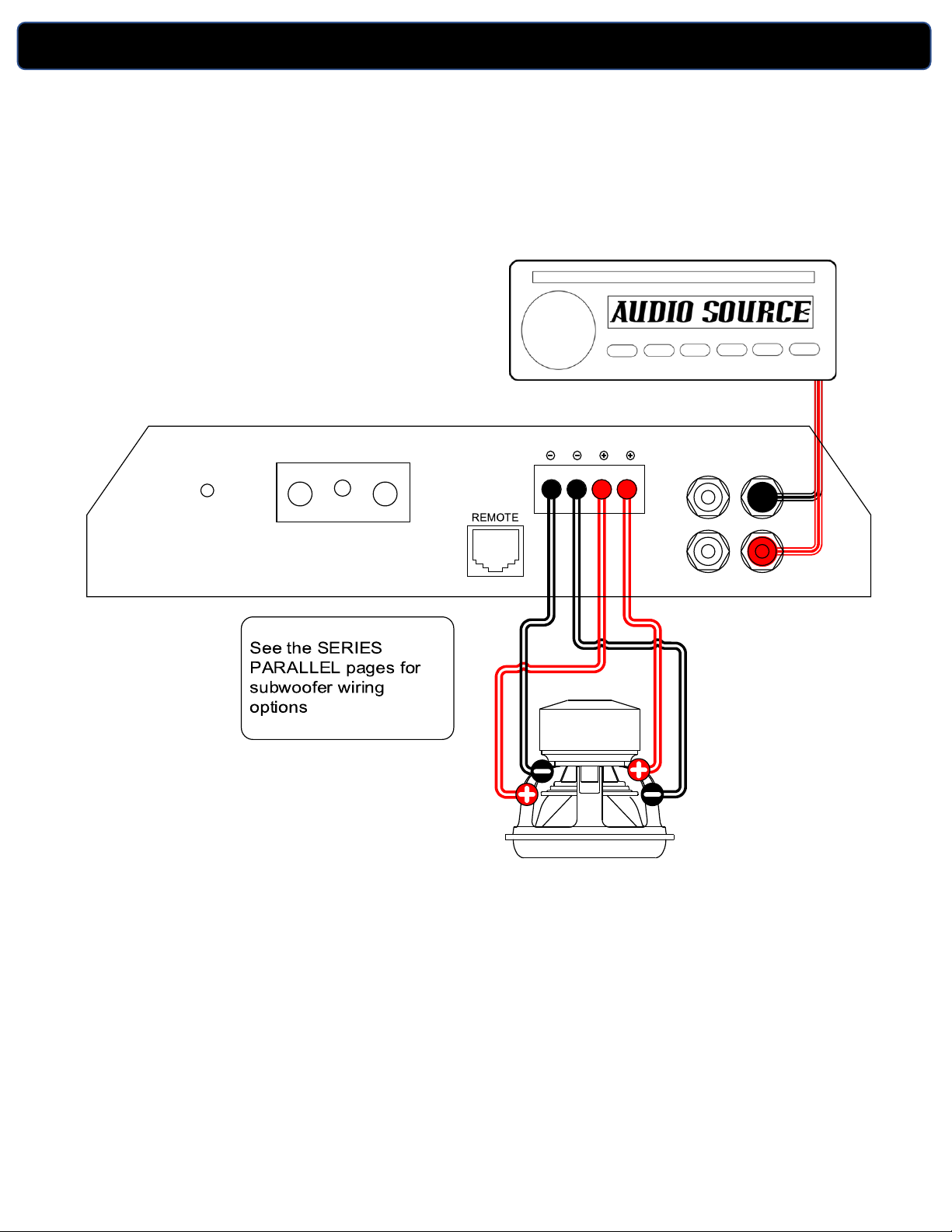
MONOBLOCK INPUT AND SPEAKER CONNECTIONS
B+
REM GND
POWER
PWR
PRT
INPUT
R R
OUTPUT
L L
SPEAKER OUTPUT

SDX SERIES AMPLIFIER OWNER’S MANUAL version 07/21 v2
MULTI CHANNEL FULL RANGE INPUT AND SPEAKER
CONNECTIONS
B+
REM GND
POWER SPEAKER OUTPUT
CH 1CH 2
SPEAKER OUTPUT
CH 3CH 4
SPEAKER OUTPUT
CH 5CH 6
PWR
PRT
CH1
CH2
CH3
CH4
CH5
CH6
5/6 CH
INPUT INPUT
3/4 CH
CH 1|2
CH 5|6
CH 1|2
CH 3|4
AUTO
SENSE
OFF

SDX SERIES AMPLIFIER OWNER’S MANUAL version 07/21 v2
Bridge mode examples for Series and Parallel wiring
MULTI CHANNEL BRIDGE MODE INPUT AND SPEAKER
CONNECTIONS
B+
REM GND
POWER SPEAKER OUTPUT
CH 1CH 2
SPEAKER OUTPUT
CH 3CH 4
SPEAKER OUTPUT
CH 5CH 6
PWR
PRT
CH1
CH2
CH3
CH4
CH5
CH6
5/6 CH
INPUT INPUT
3/4 CH
CH 1|2
CH 5|6
CH 1|2
CH 3|4
AUTO
SENSE
OFF

SDX SERIES AMPLIFIER OWNER’S MANUAL version 07/21 v2
Bridge mode example using a Dual Voice Coil Subwoofer
BRIDGE MODE INPUT AND SPEAKER CONNECTIONS
B+
REM GND
POWER SPEAKER OUTPUT
CH 1CH 2
SPEAKER OUTPUT
CH 3CH 4
SPEAKER OUTPUT
CH 5CH 6
PWR
PRT
CH1
CH2
CH3
CH4
CH5
CH6
5/6 CH
INPUT INPUT
3/4 CH
CH 1|2
CH 5|6
CH 1|2
CH 3|4
AUTO
SENSE
OFF
Ce manuel convient aux modèles suivants
6
Table des matières
Autres manuels Sundown Audio Amplificateur


