Sumitomo CAI Series Manuel utilisateur
EM0102E-4Operation Manual
Inverter CAI Series
(CAI 40/90 C Type)
CAUTION
Carefully read the “Safety Precautions” in
the introduction before reading the text
of the operation manual in order to
thoroughly understand the contents for
correct use.

[Contents]
Safety Precautions ................................................................................... 1
1. Standard specications.......................................................................... 6
2. Outline drawing........................................................................................ 7
3. Installation.................................................................................................. 8
4. Wiring ........................................................................................................... 10
5. Operation.................................................................................................... 12
6. RS485 Serial Communication ............................................................. 15
7. Alarm output ............................................................................................. 22
8. Maintenance and inspection ............................................................... 23
9. Precautions as to operation.................................................................. 24
10. Safety Guideline........................................................................................27
[Check the contents of packing]
Operation
Manual
Inveter
CAI40C/CAI90C
AC INVERTER

- 1 -
Precautions in general
Covers and safety shields have been removed in the illustrations in
the operation manual in order to show the details. Be sure to return
specied covers and safety shields to the original position before
operation. Operate the inverter in conformity with the operation
manual.
The operation manual is subject to change for improvement of the
product, change in specications, and easy use of the manual itself.
The operation manual No. will be renewed when a revised edition
is issued.
Remodeling of the inverter by the customer is beyond the scope of
our warrantee, and we will not take responsibility for any result of
remodeling.
[ Safety Precautions ]
Carefully read this operation manual for correct use before installation,
operation, maintenance, and inspection. Thoroughly understand the
inverter, safety information, and precautions before use.
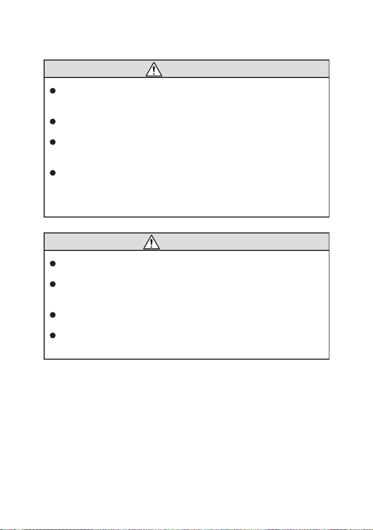
Safety precautions are classified into "DANGER" and "CAUTION" in this
manual.
: Improper handling entails danger,
possibly leading to death or serious
injury.
: Improper handling entails danger,
possibly leading to medium-degree or
slight injury or property damage.
Matters classified under CAUTION may also cause serious
results depending on the situation.
Be sure to strictly observe these safety precautions.
DANGER
CAUTION

- 2 -
(1) Conrmation of actual product
CAUTION
Do not operate the machine with a damaged inverter or an inverter
with some missing parts, otherwise injury may result.
(2) Installation
CAUTION
Attach the inverter to metal or other nonammables, otherwise a
re may break out.
Do not place the inverter near inammables, otherwise a re may
break out.
Do not hold the case at the front of the inverter, otherwise the
inverter may drop, leading to injury.
Do not allow metal chips and other foreign substances to enter,
otherwise a re may break out.
Install the inverter on a floor strong enough to withstand the
weight of the inver ter according to the operation manual,
otherwise the inverter may drop, leading to injury.

- 3 -
(3) Wiring
DANGER
Check that the input power is OFF before wiring, otherwise an
electric shock or re may result.
Be sure to install a magnetic circuit breaker (MCB), otherwise a re
may break out.
Be sure to ground the grounding terminal , otherwise an electric
shock or re may result. (200 V-class Type D grounding)
Leave the wiring work to an electric engineer.
Be sure to install the inverter before wiring, otherwise an electric
shock or re may result.
When connecting the emergency stop circuit, be sure to check the
operation of the circuit after wiring, otherwise injury may result.
CAUTION
Do not connect an AC power supply to the output terminals (U, V,
and W), otherwise injury or a re may result.
Check that the voltage of the AC power supply coincides with the
specied input voltage of the inverter, otherwise injury or a re may
result.
Do not subject the inverter to a withstand voltage test, otherwise
semiconductor elements may be broken.
Completely tighten terminal screws, otherwise malfunction, the
inverter breakdown, or a re may result.
- 4 -
(4) Operation
DANGER
Be sure to attach the case cover before turning the power on. Do
not remove the case cover during power supply, otherwise an
electric shock may result.
Do not operate switches with wet hands, otherwise an electric
shock may result.
Do not touch the inverter terminal when power is being supplied
to the inverter although the machine is at rest, otherwise an electric
shock may result.
Trip resetting by turning the power on while the operation signal is
on will make the machine resume operation suddenly. Check that
the operation signal is o before turning the power on, otherwise
injury may result.
CAUTION
Do not touch the die-cast case and radiation fin, which become
very hot, otherwise skin burn may result.
The inverter permits easy operation setting from low to high speed.
Carefully check the allowable range of the motor and machine
before setting, otherwise injury may result.
Prepare a retention brake separately as necessary, otherwise injury
may result.
Do not check signals during operation, otherwise the equipment
may be broken.

- 5 -
(5) Maintenance and inspection
DANGER
This inverter has a high-voltage terminal, which is dangerous. Do
not touch it, otherwise an electric shock may result.
Conduct maintenance or inspection ve minutes or more after the
input power is turned o, otherwise an electric shock may result.
Leave maintenance and inspection to a specialist. Remove
accessories (watch, ring, etc.) before work, otherwise an electric
shock or injury may result.
CAUTION
Semiconductor elements are used in the inverter. Handle the
inverter carefully, otherwise static electricity, etc. may break the
inverter.
Do not change wiring or attach/detach the panel while the power
is supplied, otherwise an electric shock, injury, or equipment
breakage may result.
(6) Others
DANGER
Do not remodel the inverter, otherwise an electric shock, injury, or
a re may result.

- 6 -
1. Standard specications
Product name CAI40C CAI90C
Applicable type of motor 3-phase induction motor
Applicable motor output (W) 25/40 60/90
Specication Conforming to CE mark and cUL
Output rating
Frequency (Hz) 1.0~120Hz Note:1
Output capacity (VA) 106/152 212/303
Output current (A) 0.28/0.4 0.56/0.8
Output voltage (V) Two times for 100 V class input Proportional to
input voltage for 200 V-class input
Input power
source
Voltage (V) Single-phase 100~120 V ±10% or single-phase
200~240 V ±10%
Frequency (Hz) 50/60 ±5%
Input current (A) 0.5~1.5 1.0~3.0
Control
characteristics
Control system PWM control (Pattern: V/F)
Frequency setting Front panel volume or external volume
Torque boost Low : 0 High : 8%
Over load durability 150% output for 1 min.
Acceleration/
deceleration time 0.05~30.0s Note:2
Torque setting High/Low mode setting
Front panel switch Operation stop switch and forward-reverse switch
Set signal external
terminal (8PIN)
Operation stop command, forward-reverse
command, frequency command, free-run input,
and alarm signal output
Protection
function
Details of alarm
Self-diagnosis trip, protection form overvoltage,
protection from instantaneous overcurrent,
protection from undervoltage, protection from
overload, protection of coolant from overheating,
and electronic thermal
Alarm display LED (blinking) for the front panel
Alarm output Open collector
Cooling method Self-cooling
Ambient
condition
Location of installation Indoors, Below 1000m of altitude, without corrosive
gas, liquid, or dust
Degree of contamination 2
Ambient temperature -10°C to +40°C without dew condensation or
freezing
Storage temperature -20°C~60°C
Humidity 90%RH or less
Note: 1. When driving the geared motor, use by frequency setting below the
maximum input speed of the gear.
2. No regenerative circuit for brakes is built in.

- 7 -
60.0
100.0
80.0
φ4.5
80.0
90.0
52.5
137.1
125.18.0
2.7
52.5
AC INVERTER
POWER
ALARM
RS485
RS485
POWER MOTOR
MAX
RUNSTOP
FWD REV
MIN
60.0
100.0
80.0
φ4.5
80.0
90.0
52.5
137.1
125.18.0
2.7
52.5
AC INVERTER
POWER
ALARM
RS485
POWER MOTOR
MAX
RUNSTOP
FWD REV
MIN
1.3
1.3
RS485
Unit: mm
Outline drawing
CAI40C
Weight of unit
0.30kg
CAI90C
Weight of unit
0.47kg
2. Outline drawing

- 8 -
81
+1
0
90
53
+1
0
ACINVERTER
3.1 Installation dimensions/method
Refer to Fig.(a) when installing the inverter. The inverter of the installation
surface as shown in Fig.(b).
(DIN rail cannot be attached.)
Refer to p.7 for the outside dimensions.
Secure the inverter without a gap between the inverter and the mounting
surface by using the mounting hole in the inverter.
Fig.(b)
Fig.(a)
3. Installation
Ce manuel convient aux modèles suivants
2
Table des matières
Autres manuels Sumitomo Onduleur

Sumitomo
Sumitomo HF-430NEO Series Manuel utilisateur

Sumitomo
Sumitomo SF-320 Manuel utilisateur

Sumitomo
Sumitomo HF-520 Series Mode d'emploi

Sumitomo
Sumitomo HF-430 Series Mode d'emploi

Sumitomo
Sumitomo HF-520 Series Manuel utilisateur

Sumitomo
Sumitomo HF-520 Series Manuel utilisateur

Sumitomo
Sumitomo CAI40C Manuel utilisateur


