SULO ORWAK 4240 Manuel utilisateur

Edition 9, From serial no. 121200-
Publ. no 4872223-00
OM 3110, 2015-12
Edition 3.6, From serial no. 134235-
Publ. no 4875571-00
OM 4240•4360, 2023-02
4240 • 4360
ORWAK
ORIGINAL OPERATING INSTRUCTIONS


Svetsaregatan 4
576 33 Sävsjö
Sweden
Type
Serial No
Product No
Date
V
Weight
Hz
kW A
*
* *
***
Temperature range of use (special oil): -10°C to +40°C
Temperature range of use (standard oil): +5°C to +40°C
~
A
+40 °C
+5 °C -10 °C **
**
3
IDENTIFICATION
You nd the serial number on the baler.
For any inquiries, please indicate the type and
serial number of the baler.
Svetsaregatan 4
576 33 Sävsjö
Sweden
Type
Serial No
Product No
Date
V
Weight
Hz
kW A
*
* *
***
Temperature range of use (special oil): -10°C to +40°C
Temperature range of use (standard oil): +5°C to +40°C
~
A
+40 °C
+5 °C -10 °C **
**
* - XXXX (ex Compactor 4240)
** - XXXXXX (ex 121001)
*** - 490XXXX - XX (ex 4904240-00)
English
Safety information........... 14
Parts of the machine....... 15
Safety.............................. 16
Control panel .................. 17
Operating instruction....... 18
Weekly inspection and
maintenance ................... 19
Technical specication.... 20
Dimensional drawing...... 20
Transport ........................ 21
Installation ...................... 22
CE.......... ......................... 23
Electrical diagram
Hydraulic diagram
CONTENTS
Errors and omissions excepted.
IDENTIFICATION
You nd the serial number on the baler.
For any inquiries, please indicate the type and
serial number of the baler.
* - XXXX (ex Compactor 4240)
** - XXXXXX (ex 121001)
*** - 490XXXX - XX (ex 4904240-00)
English
Safety information........... 4
Parts of the machine....... 5
Safety.............................. 6
Control panel .................. 7
Operating instruction....... 8
Weekly inspection and
maintenance ................... 9
Technical specication.... 10
Dimensional drawing...... 11
Transport ........................ 12
Installation ...................... 13
CE.......... ......................... 14
Electrical diagram
Hydraulic diagram
CONTENTS
Errors and omissions excepted.

4875539-00 4875543-00
4
English
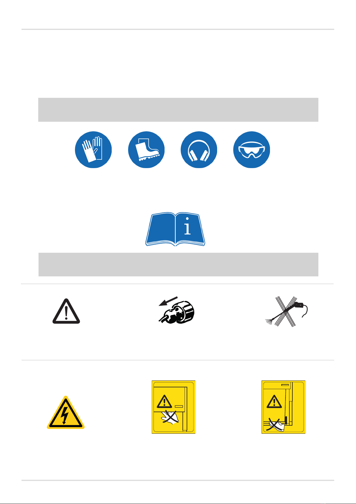
OPERATOR WARNING & DUTY
This manual must be available permanently near the baler. Each operator must read and follow
the full instruction of this manual before being authorize.
All operator must absolutely study and fully understand the operator’s manual, specically pay
a particular attention to the safety procedure section.
In case of misunderstanding or doubt, do not start the machine. Contact support service.
Operators and service sta must comply by wearing personal protective equipment (PPE)
before using or performing any maintenance operation following rule and regulation code.
Operator and service personal must be trained during the commissioning on the baler
operation, by a duly authorized person from the manufacturer.
To avoid any mistake or accident, all operators must understand the operator manual.
All operators must absolutely study and fully understand the operator’s manual.
This manual must remain available for any personal involve with the baler.
SAFETY SIGN - In the manual
SAFETY SIGN - On the baler
Warning !
Danger High Voltage
Do not ush water
on the baler.
During inspection and maintenance,
servicing and removal of trapped waste.
Disconnect the power to the machine by
removing the plug from the wall socket.
Warning! Beware of your hand
when the machine is in motion.
Warning! Beware of your foot
when the machine is in motion.
14
4

5
English
Press
plate
Friction plate
Foot
Front shutter
Control panel
Emergency stop
Rear shutter
Shutter
Press unit
Wheel
Indication plate
Apron
(double machine)
Hydraulic unit
PARTS OF THE MACHINE
15
5

6
Please read the operating instructions BEFORE operating the machine.
Our warranty/product responsibility requires that:
• instructions are followed, and that no conversion or modication is carried out.
• original spare parts, and hydraulic oils and lubricants recommended by the
machine manufacturer are used.
• at least one annual service is carried out.
The user of the machine is responsible for the safety checks, and for ensuring that daily
maintenance of the machine is carried out.
The user is responsible for making sure that defects are rectied, and that neither the
user nor otherpeople are exposed to danger.
The owner is responsible for ensuring that all laws and instructions are complied with
when using the machine.
This symbol means WARNING or DANGER – personal safety
instruction!
This machine is designed for ONE-MAN OPERATION.
Only the operator is allowed in the working area of the machine. The working
area is dened under the heading Technical data; Recommended space for
machine in operation.
The machine must not be operated if the safety features (e.g. breakers and
guards) have been deactivated, damaged or removed.
Lost or damaged parts must be replaced with original spare parts.
The machine may only be operated by a person who has received training
and has experience with the machine.
The machine has a high centre of gravity, handle the machine with
caution when moving. The area immediately around the machine and its
base should be completely level.
Installation, repair and service must only be performed by qualied and
competent personnel, and in accordance with the installation and
service instructions.
The machine must not be used by minors.
Never climb on the machine!
Avoid compacting materials of dierent hardness in the machine at the same
time. (If the waste has not been properly mixed and distributed well in the
chamber, it can result in an uneven load on the press plate and damage to
the machine).
The machine should be anchored at the time of installation.
SAFETY FEATURES
The machine is equipped with the following safety eatures: a breaker switch that prevents
the machine from being used when the upper door is open; mechanical door interlocks,
and guards and doors to protect against dangerous intervention in the machine. The
machine is also equipped with an emergency stop. The above safety features must be
checked regularly; see section on weekly inspection and maintenance.
SAFETY
English
16
6

7
CONTROL PANEL
Bale size - this feature
is not used on this
machine.
Arrow up - used to
raise the press plate to
its normal position.
Arrow down - used to
lower the press plate.
The press plate stops
in its down position.
Start - starts a
compaction cycle.
Steady light
- the machine
is ready for use.
Blinking light
- the door must be
opened and closed
for the press cycle to
be able to start.
Emergency stop
- used if a compaction
cycle has to be
stopped immediately.
The LED lights when
the emergency stop is
pressed.
If the LED remains lit
when the emergency stop
is cancelled, there is a fault
in the machine. Call an
authorised technician.
Bale light
- this feature is
not used on this
machine.
Service light
– see under
TROUBLESHOOTING
below for more
information.
MAN/AUTO
- this feature is not used.
To start a compaction cycle,
the start button
must be pressed.
Temperature lights
Blue lights indicate that the machine is cold.
The machine can still be operated.
Red light indicates that the machine has
overheated and CANNOT be operated
until it has returned to its normal temperature and
the light has gone out.
Voltage light - this light
indicates that there is
power to the machine.
PAPER/PLASTIC
- this feature is not used,
since this machine presses
dierent types of materials
at the same time.
English
RANGE OF APPLICATION
The machine is a hydraulically operated baler intended for compacting bulky materials such as cardboard, paper
and plastic. The machine may only be used in areas that have a roof, protection against wind, and normal light-
ing. The machine is intended for use within the temperature range -10°C to +40°C.
A low-temperature oil and/or heater should be used at temperatures lower than +5°C.
Materials that are ammable or of an explosive nature, such as pressurised containers or the like, which could
cause injury, damage, re or an explosion if exposed to pressure or sparks, must not be compacted in the
machine.
TROUBLESHOOTING
Flashing service light = fault.
Fault messages can be read via the service light.
First, try removing the plug from the mains and then plugging it back in.
If the fault persists and the service key ashing again don’t turn of the power: instead press the emergency stop
button, after some seconds there will be a number of ash¬es, e.g. LED extinguished for 5,10 or 15 seconds
followed by 1 to 9 ashes. (Example 5 second 3 ash or 10 seconds 2 ash.)
For optimal service help – mention the ashing message when reporting the fault.
Do not use the machine until an authorised service engineer has corrected the fault.
Service light, steady light = time for servicing. Contact your authorised service engineer.
The machine can continue to be operated.
17
17

7
1 2
56
8
English
Compaction
Lock the front shutter before start.
1Distribute the waste evenly
inside the bin.
2Place the bin in the machine
and close the door.
The start button will glow green
- press the start button for a
compaction cycle.
WARNING!
Only the operator
is allowed in the
working area
of the machine!
OPERATING INSTRUCTIONS
SINGLE
Empty bin
3Open the door and pull out the
bin.
4Empty the bin and put it back in
the machine.
Compaction
Lock the front shutter before start.
5Place the bins in the
machine.
6Distribute the waste evenly
inside the bin.
7Slide the press unit to the
side you want to press.
The start button will glow
green
- press the start button for
a compaction cycle.
DOUBLE
Empty bin
8Slide the press unit to the side
and pull out the bin.
9Empty the bin and put it back
in the machine.
18
8

A
B10A
9
English
NOTE!
During inspection and maintenance, service and the removal
of trapped waste etc:
1. Disconnect the power to the machine by removing the
plug from the wall socket.
2. Do not work inside the machine.
ANNUAL CONTROL
The annual machine inspection should be performed by an
authorized service technician approved by the manufacturer.
WEEKLY INSPECTION AND MAINTENANCE
- Check the shutter switch: it must not be possible to start the machine if the upper
shutter is open/opened.
- Check that the emergency stop is working.
- Check that all covers and guards are intact.
- Check that there are no oil leaks on the machine.
- Check that the electrical supply cable is intact and properly protected against impact.
If any faults are discovered in the functions listed above, the machine must not be used
until it has been repaired by authorised service personnel.
Flashing service light = fault.
Fault messages can be read via the service light.
First, try removing the plug from the mains and then plugging it back in.
If the fault persists and the service key ashing again don’t turn of the power: instead press the
emergency stop button, after some seconds there will be a number of ashes, e.g. LED extinguished for
5,10 or 15 seconds followed by 1 to 9 ashes. (Example 5 second 3 ash or 10 seconds 2 ash.)
For optimal service help – mention the ashing message when reporting the fault.
Do not use the machine until an authorised service engineer has corrected the fault.
Service light, steady light = time for servicing. Contact your authorised service engineer.
The machine can continue to be operated.
When changing the oil: Contact the local authorities for guidance regarding the
environmentally correct disposal of waste oil.
Miscibility must be taken into account when changing and/or topping up the oil.
The machine comes lled with mineral oil from the factory.
TROUBLESHOOTING:
First, check:
OVERLOAD PROTECTION
TRIPPED
NORMAL
FUSE
SAFETY CHECKS
19
9

1515
920
2100 (+175)
750
1060 (+175)
900
1475
990
1250 (+175)
2100 (+175)
G
D
E E
CB
A
A
10
English
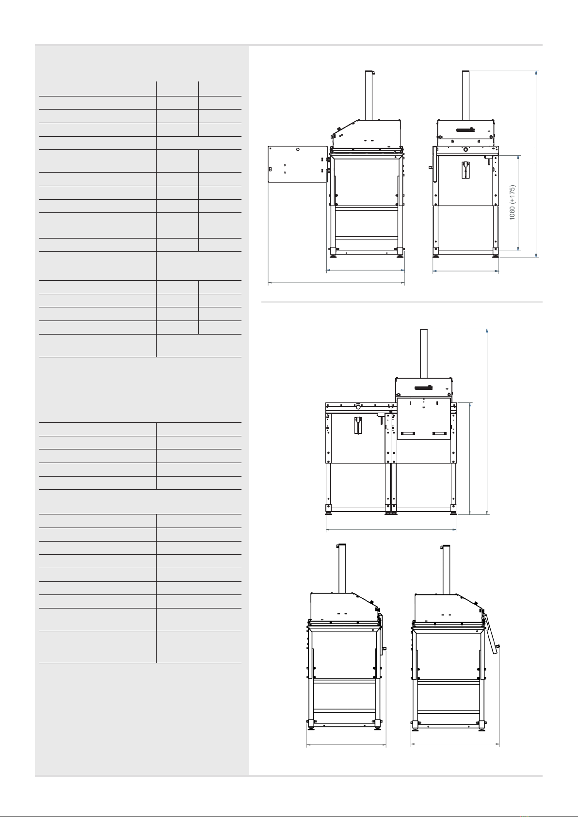
TECHNICAL
SPECIFICATIONS DIMENSIONAL DIAGRAM
SINGLE
DOUBLE
GENERAL DATA 4240 4360
Total weight single: 220 kg 240 kg
Total weight double: 320 kg 360 kg
Transport height: 2,100 mm 2,100 mm
Dimensions:
A - Height, min:
max:
2,100 mm
2,275 mm
2,100 mm
2,275 mm
B - Width single: 750 mm 950 mm
C - Depth single 920 mm 980 mm
D - Width double: 1,475 mm 1,900 mm
E - Depth double, min
max
900 mm
990 mm
970 mm
1060 mm
Depth with open door: 1,515 mm 1,790 mm
Recommended space
for machine in operation
(working area):
Height: 2,275 mm 2,275 mm
Width single: 1,950 mm 2,150 mm
Width double: 2,675 mm 3,100 mm
Depth with open door: 2,115 mm 2,390 mm
Noise level: < 62,3 (± 1.0) dB (A)
(ISO 11200 & 11202)
Paint:
Two-part paint and powder coat with
phosphatising as base.
ELECTRICAL DATA
Operating power: 230V, 50Hz
Operating voltage: 24V
Electric motor: 1,1 kW
Fuse rating: 10A
Protection class: IP 55
HYDRAULIC DATA
Working pressure: 55 bar
Overload pressure: 90 bar
Press force: 1.5 ton
Surface pressure: 1,17 kg/cm2
Cycle time total: 29 sek.
Cylinder stroke length: 640 mm
Oil volume: 6,0 liter
Recommended oil:
+5°C till +40°C
ISO VG 32-68,
Mineraloil
Below +5°C A special oil or heater
should be used at
lower temperatures.
20
10
Ce manuel convient aux modèles suivants
1
Table des matières
Manuels Compacteur de déchets populaires d'autres marques

Whirlpool
Whirlpool GX900QPLQ - 15" Trash Compactor Manuel utilisateur

Vestil
Vestil FM-T-DUMP Manuel utilisateur

GE
GE GCG1700P Manuel

Euro Shatal
Euro Shatal RP4014-50 Manuel utilisateur

third coast equipment
third coast equipment SP3410 Manuel utilisateur

Cucine Oggi
Cucine Oggi EKKO CUBE 40 9000 Manuel utilisateur