Operation
5 Installation and connection
5.1 Preparations for installation
5.1.1 Check operating conditions
1. Ensure the required operating conditions are met:
– Resistance of body and seal material to the medium
(→ resistance lists).
– Media temperature (→ Data sheet)
– Operating pressure (→ Data sheet)
2. Consult with the manufacturer regarding any other use of
the device.
5.1.2 Preparation of the device
1. Ensure the device is protected against ingress of moisture.
2. Cut the probe rods to length if necessary. Check the appli-
cation examples for the relevant type (→ 9.2.1 Description
of the contact points, Page 8 ).
3. Check that the uninsulated ends of the rods are not touch-
ingeachother.
5.1.3 Preparation of the vessel
The device can be installed in closed and open containers.
Wheninstalledinanopenvessel,thedeviceshouldbe
mounted on a suitable bracket (such as the PE installation
kit).
1. When installed in an enclosed vessel, ensure the approved
installation thread diameter G 1" is provided.
2. Check that the vessel provides sufficient immersion depth.
3. Align the vessel correctly, ensuring the following points are
satisfied:
– The device must be mounted perpendicular to the sur-
face of the medium
– Sufficient space for installation, electrical connection
and maintenance
5.2 Install device
The device installation is complete.
WARNING
Risk of injury and poisoning due to medium spraying out!
Use personal protective equipment when carrying out any
work on the fitting.
NOTE
Incorrect installation can lead to material damage!
Do not grip the top part of the housing to screw in the
device.
Insert a screwdriver into the process connection in order
to screw in the device perpendicular to the surface of the
medium.
5.3 Electrical connection
Cable without shielding can be used to connect the device.
If electromagnetic interference is anticipated, or if the cable
lengths are greater than 30 m, shielded cable should be
used.
The unit must be installed properly.
Power supply switched off and secured against being
switched back on again.
1. Unscrew the housing cover.
2. Guide the connection cable through the cable glands and
connect:
– Connection cable (→ Data sheet)
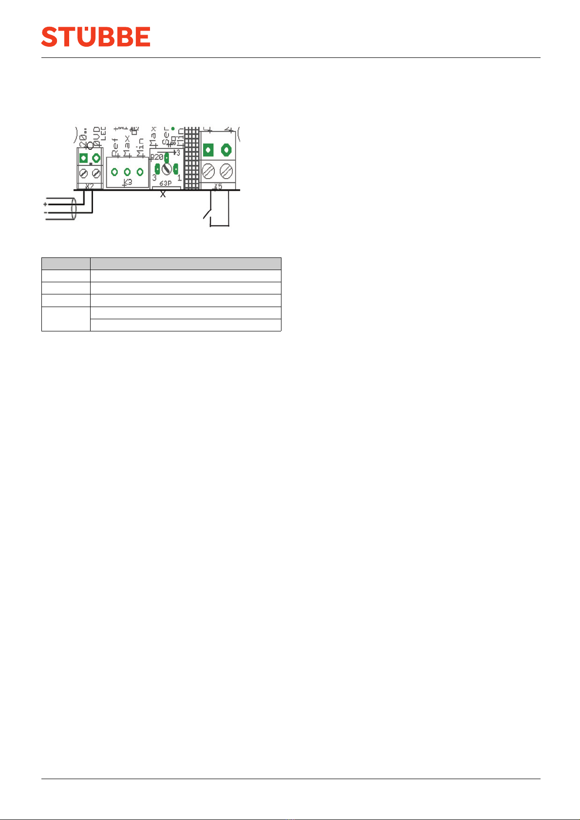
– Description of the contact points and circuit diagrams
(→ 9.2 Connection diagrams, Page 8 ).
3. Tighten the cable glands securely.
4. Screw on the housing cover.
6Operation
6.1 Configure device
If the medium exhibits either low conductivity or high con-
ductivity, it will be necessary to adjust the sensitivity using
the potentiometer.
The potentiometer is described in the connection diagrams
(→ 9.2.2 Connection diagrams, Page 8 ).
The device is installed and connected.
1. Fill the vessel until the medium makes contact with the
probe rods.
2. Unscrew the housing cover.
3. Switch on power supply.
4. To increase the sensitivity, turn the potentiometer clock-
wise.
5. To decrease the sensitivity, turn the potentiometer anti-
clockwise.
The LEDs indicate that the respective limit level has been
reached.
6. Switch off power supply.
7. Screw on the housing cover.
6.2 Commissioning
The device is installed and connected.
The device has been adjusted.
Switch on power supply.
When the medium makes contact with the sensor rods, the
device will indicate the minimum or maximum filling level.
If the device is fitted with a 2-state control unit, the corre-
sponding circuit will be activated.
6 CFP BA-2022.08.31 EN 302 483