
Strong Super Trouper Manuel utilisateur

FOLLOW SPOTLIGHT
INSTRUCTION MANUAL
4350 McKinley Street • Omaha, Nebraska 68112 USA
Tel (402) 453-4444 • Fax (402) 453-7238 • www.strong-lighting.com
Equipment Type 7201156 • Rev. October 2010


PREFACE
THESTRONGXENONSUPERTROUPER®isadirectcurrentfollowspotlight
systemcompletewithaxenonlamphouse,powersupply,opticalsystem,andaoorstandandyoke
assembly.Anoptionalsix-color,selfcancellingboomerang(OrderNo.7201188;seeFigure7)may
beorderedwithnewequipment,oritcanbeaddedatalaterdate.
ONLY THE SPECIAL XENON POWER SUPPLIES manufactured by Strong
Internationalcanbeusedwiththexenonspotlight.
Forinstallationandoperationofthepower
supply,seetheinstructionmanualfurnishedseparately.
THEXENONLAMPHOUSEutilizesadeepellipsedichroicmetalreectordesignedto
operateinaxedpositionwithahorizontallymountedxenonbulbasthelightsource.Aheatlteris
locatedinthefrontofthelamphousetoreducetheheatattheopticalsystemandcolorboomerang.
ONLY XENON BULBS designed for horizontal operation should be used in this
spotlight.Thelamphouseisdesignedforusewiththestandard2000watthorizontaltheatrebulb,
andanoptionalAdapterKit(OrderNo.7201192)allowsuseof1000and1600wattbulbs.Seethe
listinginthismanualfortheapprovedtypesandnecessaryadapters.
ADJUSTMENTCONTROLforpositioningthexenonbulbislocatedattherearof
thelamphouse.Theadjustmentsareforthehorizontal,vertical,andfocuscontrolofthebulb.
THELAMPHOUSE INSTRUMENTPANELisequipped withan ammeterand
runningtimemeter.Theammeterindicatestheoperatingcurrentofthelamp,andtherunningtime
meterrecordsthenumberofhoursthelamphasoperated.Thexenonbulbisignitedandextinguished
byuseoftheLAMPswitchmountedontheinstrumentpanel.
THELAMPBLOWER,internallywiredinthelamp,operateson115V.ACandis
requiredtokeep thesealson thebulbatasafeoperatingtemperature. Thisblower willoperate
continuouslyuntilpoweristurnedoffatthemainlineswitchtothexenonpowersupply.Anair
owswitchinthelamphousepreventsoperationofthexenonlampiftheblowerisnotoperating,or
ifairowisinadequate.Ifadditionalcoolingisrequired(i.e.50Hertzpowersource),anoptional
ExhaustBlowerAssembly(7201036;seeFigure8)maybemountedtothetopofthelamphouse.
THELAMPHOUSEissuppliedwitha11foot(3.35m)cablecontainingthetwoDC
leads,thegroundlead,andallACcontrolleads.Thecableterminatesinamultiple-pinMSconnector
tomatetoacorrespondingreceptacleonthexenonpowersupply.
WHENTRANSPORTINGthefollowspotlight,itisrecommendedthatthexenonbulb
beremovedfromthelamphouseandplacedinitsoriginalshippingcartonwiththeprotectivecover
onthebulbtopreventbreakage.
XST/001
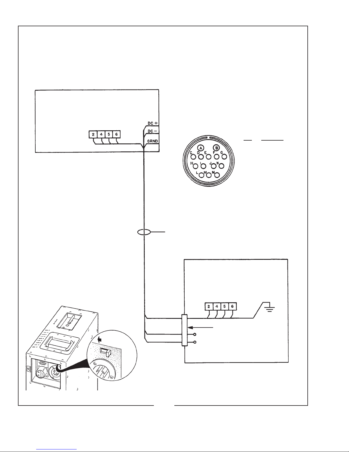
LAMPHOUSE - POWER SUPPLY
Interconnection Diagram
LAMPHOUSE
(Connections Pre-wired)
MS CONNECTOR
Pin Wire No.
A DC-
B DC+
C 2
E 4
F 5
G 6
M Grnd
Lamphouse
Cable Assembly
XENON
POWER
SUPPLY
MS Connector (pre-wired)
DC+
DC-
XST/002
SYSTEM MUST BE GROUNDED
All wiring must conform to local codes;
shield lamphouse cable in conduit if
required.
Check Slide Switch (below) on Power
Supply for correct “SPOT” position.
Slide to LEFT

XST/003
INSTALLATION AND SETTING UP SPOTLIGHT
THEXENONSUPERTROUPERisshippedinsectionswhichmustbeassembled.
TheFoldingBaseStandAssembly65826000(seeFigure6)isshippedcollapsed,andrequiresonly
foldingdownandpinningthefourbaselegs.
WHENINSTALLEDinapermanentlocation,thelevelingfeetmustberemoved,and
theclearanceholesinthebaselegbracketsusedforhardware(usersupplied)toboltthebasetothe
oororplatform.Ifitisdesiredtohavetheunitportable,whenoperating,thelevelingfeetmustbe
adjusteddownuntiltheweightofthespotlighthasbeenshiftedfromthecasterstothelevelingfeet.
THEINNERTUBEandsupportyokehasthreeholestopermitadjustingtheheightof
thespotlight.Thethreeholesareonfour-inchcentersandwillallowanopticalheightofapproximately
53inches,57inches,and61inchesaboveoorleveltotheopticalcenterofthelamphouseandlens
system.Thelevelingfeetmaybeadjustedthroughanadditionaltwoinchrange.Inserttheheightloca-
tionpin(Figure5,Item16)throughtheholeintheoutertubeandoneoftheholesintheinnertube.
THEHORIZONTALSWINGandverticaltiltlockingknobsareontherighthand
(operating)sideoftheyokeassembly.Tightenbothoftheselockingdevices(Figure6,Items19&
21)securelybeforeattemptingtoplacethelamphouseandlenssystemonthesupportyoke.
PLACETHELAMPHOUSEandlenssystemontheyokeassembly(Figure6,Item4),
withthespotsizecontrolhandletotherighthand(operating)side,thesameasthelockingcontrols
ontheyoke.Lineupthefourmountingholesinthebottomofthebaserailwithfourslottedholesin
thesupportyokeandsecurewiththefour5/16-18wingscrews.Thereare(2)setsoffourmounting
holestoinsurecorrectbalanceofthespotlightwithorwithouttheoptionalcolorboomerang.An
optionalCounterweightKit(7201191)isalsoavailableforsettingconcisebalanceadjustments.
THEOPTIONALCOLORBOOMERANG(7201188)mountstothefrontopening
oftheopticalsystemonthreestudsprotrudingfromthefrontoftheopticalsystemhousing.Secure
theboomerangusingthe(3)screwsprovided,andinstallthesafetycablebetweentheboomerang
housingandthespotlightframe.
ATTACHTHELAMPHOUSECABLECONNECTORtothereceptacleonthexenon
powersupply.Alignthepinsbeforetighteningthelockingring.Donotenergizethepowersupply
beforerstcompletingthebulbinstallationprocedure.
CHECKTHE“CONS/SPOT”SLIDESWITCHonthexenonpowersupplycabinet
andverifythatithasbeenplacedintheappropriate“SPOT”position.Seetheillustrationonthe
insidefrontcoveroftheXenonPowerSupplyinstructionmanual.
SAFETY PROCEDURES
THEXENONBULBishighlypressurized.Whenignited,thenormaloperatingtemperature
ofthebulbincreasesthepressuretoalevelatwhichthebulbmayexplodeifnothandledinstrictaccordance
tothemanufacturer’soperatinginstructions.Thebulbisstableatroomtemperature,butmaystillexplodeif
droppedorotherwisemishandled.
REFERbulbreplacementandservicetoQUALIFIEDPERSONNELwithadequateprotec-
tiveclothing(faceshield,cleancottongloves,welder’sjacket).Forroutinelamphouseservice,observethe
followingrules:
1. Allowthebulbtocooltoroomtemperaturebeforeopeningthelamphouse.Putonprotectiveclothing
describedabove.
2. De-energizethexenonpowersupplyattheACsourcebeforeopeningthelamphousecompartment.
3. Whenpossible,encasethe bulb in its protectivecover whencleaning orservicing the lamphouse
interior.Thebulb,whenoutsidethelamphouse,mustbeencasedinthecover.
4. Cleanthebulbafterithascooledtoroomtemperature.Donottouchthequartzenvelopeofthebulb;
ngerprintswillburninandcreatehotspotswhichmayshortenbulblife.Ifngermarksaremade,
theyshouldbecarefullyremovedwithmethylalcoholandcottonpriortobulboperation.
5. Neverviewanignitedbulbdirectly.BLINDNESSORPERMANENTEYEDAMAGEMAYBE
INCURRED.
6. UseonlyxenonbulbsdesignatedasOZONEFREE.Whenpossible,ventthelamphouseexhaustto
outsideatmosphere.
7. Maintainthelamphousebloweringoodoperatingcondition.Keeptheblowerinletcleanforunre-
strictedairow.
8. Toinsuremaximumbulblife,operatethelamphouseblowerandtheexhaustsystemforat leastten
minutesafterextinguishingthebulb.
9. Ifreturningabulbforwarrantyadjustment,packitinitsoriginalshippingcontainer.Completeand
returnallrequiredwarrantyinformation.
10. Disposeofexpiredbulbsthatarebeyondwarrantyinthefollowingmanner:Wrapthebulbtightly
inseverallayersofcanvasorheavycloth.Placeitonahardsurfaceandshattertheenvelopewitha
sharphammerblow.DONOTplaceanunshatteredbulbinanordinaryrefusecontainer.
11. DONOTPERMITUNAUTHORIZEDPERSONNELTOPERFORMORATTEMPTANYPHASE
OFXENONBULBHANDLINGORSERVICE.
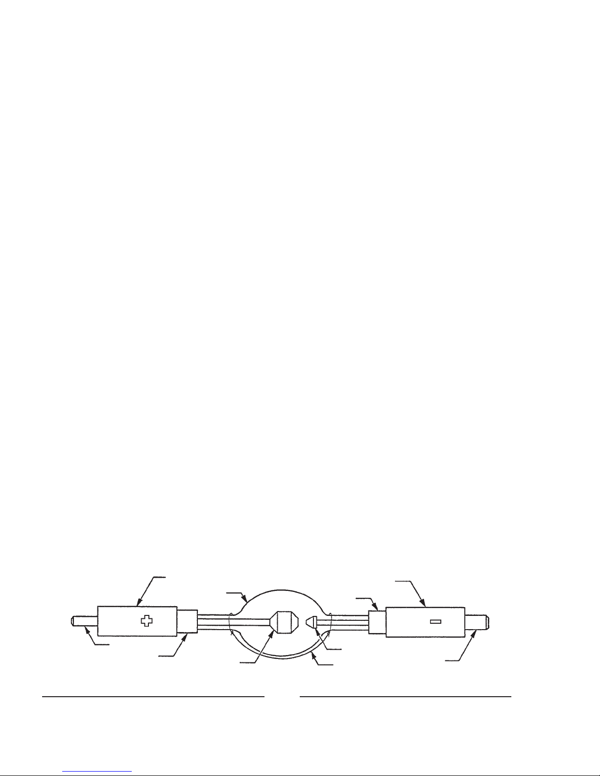
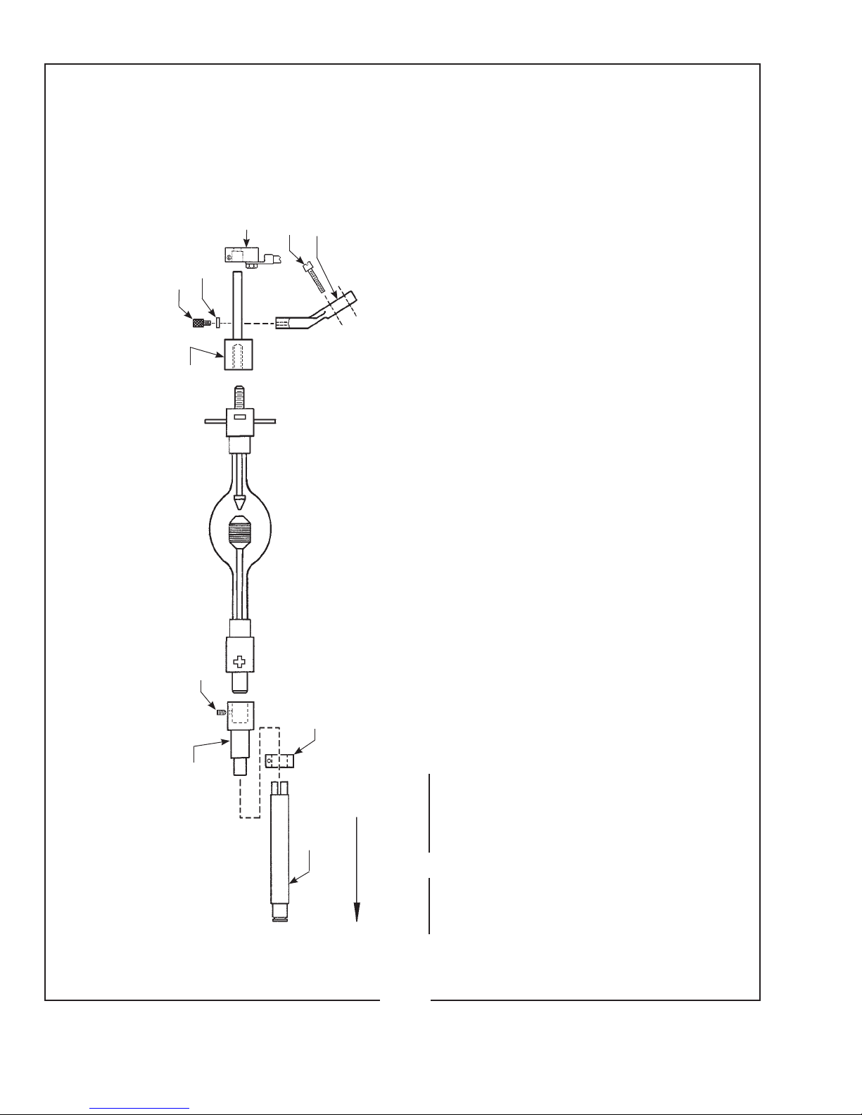
Cathode End Cap
Envelope
Anode End Cap
Anode Pin
Seal Anode
Cathode
Trigger Wire Cathode Pin
Seal
XST/004
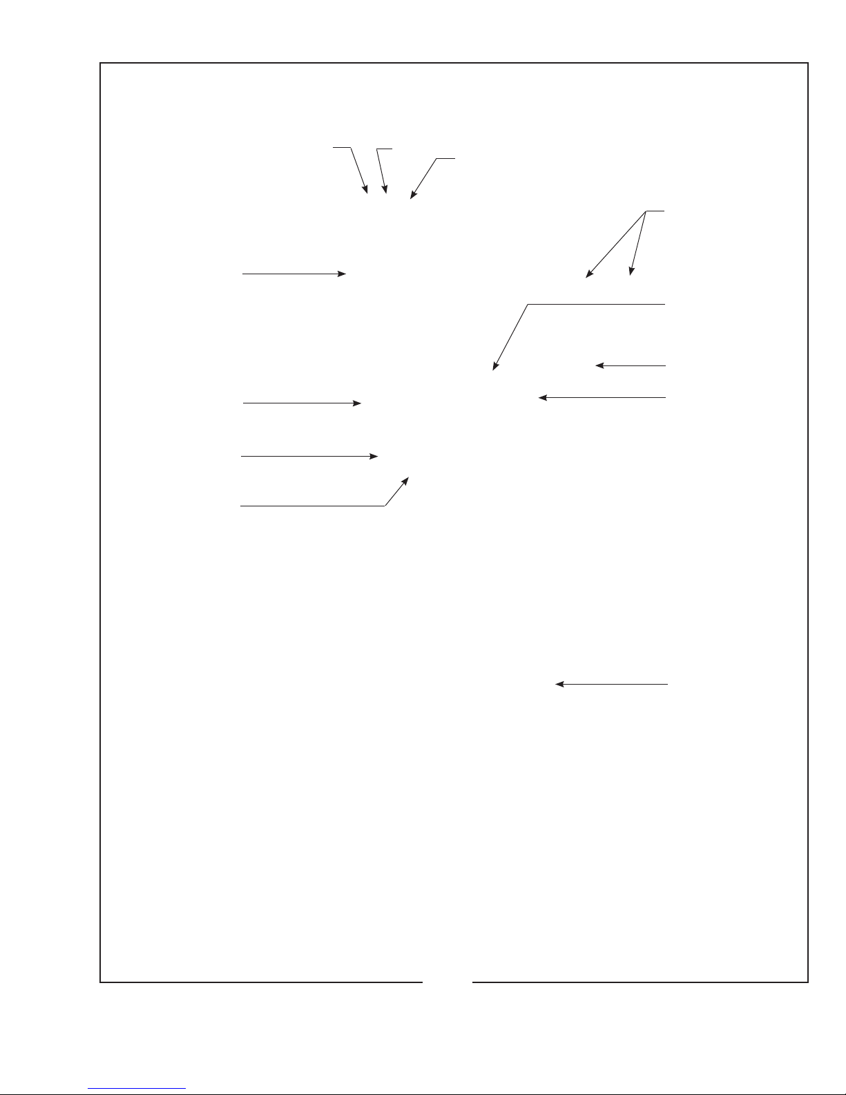
1.Fade-OutMechanismControlLever
2.MaskingShutter(Chopper)ControlLever
3.IrisControlLever
4.BoomerangMountingStud,Upper*
5.SpotSizeControlHandle
6.BoomerangMountingStud,Lower*
XST/005
2
13
4
5
6
7
8
9
10
11
12
7.SpotFocusControlKnob
8.LevelingFoot
9.HeightAdjustPin
10.HorizontalSwingControlLever
11.VerticalTiltControlLever
12.LiftingStrap
*ColorBoomerangoptional;seeFigure7

EXHAUST SYSTEM INSTALLATION
IFTHESPOTLIGHTisinstalledinaclosedbooth,itisrecommendedtoventthe
lamphouseexhausttooutsideatmospheretoremovetheheatfromthebooth.Anoptionallamphouse
topcoverplatewithanexhauststack(PartNo.7201222)maybeorderedfromStrongandinstalled
inplaceofthestandardtopcoverplate(seePartsList,Figure2,Item27).
THEEXHAUSTSTACKoftheoptionallamphousecoverplateisdesignedtota
six-inchdiameterduct.Theexhaustsystemmustbedesignedandinstalledisamannerastoelimi-
nateanypossibilityofadowndraftorofraindrippingintothelamphouse.Theexhaustfanmustbe
capableofremoving750linealfeetperminute(150cfm)ofairfromeachlamphouse.
TO PERMIT MOVEMENT of the follow spotlight, install a section of six-inch
diameter,non-ammable,exibleductingbetweenthelamphouseexhauststackandtheprojection
boothexhaustsystem.Twoscrewholesintheexhauststackcanbeusedtosecuretheductingwith
#6self-tappingsheetmetalscrews.
IFADDITIONAL BULB COOLING is required (i.e. 50 Hertz power source), an
optionalExhaustBlowerAssembly(PartNo.7201036;seeFigure8)maybemountedtotheexisting
topcoverofthelamphouse.Whenconnectingtheblowerleads,makecertainthewiresaredressed
behindthereectorsupportcastingtopreventheatdamage.Thisblowerassemblyexhaustsintothe
surroundingairanddoesnotallowconnectiontoaductedexhaustsystem.
THERADIATIONfromsomexenonbulbscanconverttheoxygeninthesurrounding
airtoozone.Inlargequantities,ozonecanendangerhealth,butitspontaneouslychangesbackinto
oxygeninaveryshorttime,especiallyifitmixeswithalargevolumeofair(asinanauditorium,
arena,oroutdoors).Mostcurrentlymanufacturedxenontheaterbulbsareclassiedasozone free
anddonotreleaseozone.
XST/006
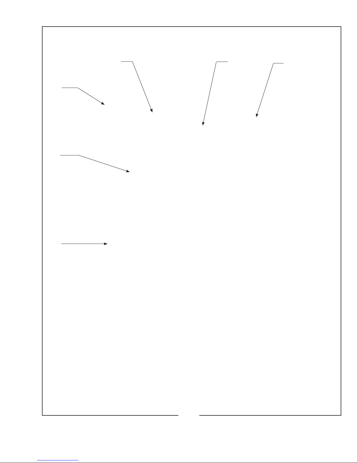
1.LAMPSwitch(ON-OFF)
2.Ammeter
3.AirIntake,Blower
4.Cover,BulbAdjustControls
5.TopCover,Lamphouse
6.ElapsedHourMeter
XST/007
12
3
4
5
6
XST/008
1000, 1600 WATT BULB INSTALLATION
Requires optional Bulb Adapter Kit 7201192
65960000* 65131000
4100180
65199000
REAR OF LAMPHOUSE
OBSERVE CORRECT POLARITY
65117000*
4110750
65198000 65152A00
65151000
65148000*
1000 Watt Operation: 50 Amperes Nominal
DO NOT EXCEED 58 AMPERES
1600 Watt Operation: 65 Amperes Nominal
DO NOT EXCEED 70 AMPERES
PartNo. Description
65117000 BulbSupportYoke
65131000 Anode(+)ContactClamp
65148000 Cathode(-)ContactClamp
65151000 RetainerPlate
65152A00 Thumbscrew(2req’d.)
65198000 CathodeAdapter
65199000 AnodeAdapter
65960000 RearBulbSupportCollet
4080870 ClampingScrew(for65131000&65148000)
4100180 SetScrew,AnodeAdapter
4110750 BulbSupportMountingScrew
4250373 LeadMountingScrew(for65131000&65148000)
NOT SHOWN
65948000 Negative(-)LeadAssembly,29"(ClamptoShunt)
65966000 Positive(+)LeadAssembly(incl.65131000)
* Replace Collet, Front Bulb Support, and
Cathode Clamp before installing bulb.
Table des matières
Autres manuels Strong Équipement d'éclairage


Manuels Équipement d'éclairage populaires d'autres marques


Qazqa
Qazqa Suplux SL 3 Black 103062 Manuel utilisateur

Commercial Electric
Commercial Electric 54568141 Manuel utilisateur

CREE LIGHTING
CREE LIGHTING 304 Series Manuel utilisateur

Goobay
Goobay 49867 Manuel utilisateur

ECOMAN ITALIA
ECOMAN ITALIA LED T8 Manuel utilisateur

Alkalite
Alkalite Krypton KT-81 Manuel utilisateur


