7 | Page
WATER AND ELECTRICITY INSTALLATION INSTRUCTION FOR ALL MODELS
(1) Water: Two water lines forcold and hot water respectively ½-inch National PipeThread(NPT).
(2) Power:Power requirement: Single-phase three-wire 220V power supply.
TECHNICAL INFORMATION
•Materials: Tempered Glass
•Power Supply: 3KW 20amp, 220V
•Steam Ready: 2-5 MIN
ELECTRICAL INFORMATION
•1 dedicated 12-2 line for steam (line 1, line 2, and ground)
•Single-phase three-wire 220 volt, 20 amp GFCI breaker
•The length of the wire for the machine is 1.5m (adjustable); it can be changed to a suitable length.
•Connect the overhead light, speaker, fan, CD, telephone according to the tags on the wires.
•Do not connect the wire “O3” to anything.
•Connect main power supply.
PLUMBING INFORMATION
•The unit is equipped with 3 ft. hot and cold, metal braided water supply hose with ½-inch national pipe thread to connect from
faucet/manifold (Manifold is located. 4 ft. high on rear of unit) to the shutoff valves (should be installed where they can be
accessed). Note: base edge sets directly against back and sidewall. Donot install any pipes along walls as to impede the
base from setting flush against them..
•Install hot and cold shutoffs with ½ -inch male national pipe thread (not included).Install shutoffs wherethey can be
accessible.
•Access panel near controls, pumps, and jets is recommended
•Drainage: It isadvised to have baseonsite before preparingdrain location. The diameter of the drain hole should be larger or
equal to Φ40mm (1.6 inches).
•Note: The flexible drain hose included with this unit is for installation into a floor drain only.
Substituting the existing drain setup for a setup of the installers’ choice will not void the warranty of
the unit as long as there is no evidence of misuse or damage to the base..
•All fixtures and fittings must be checked for tightness as they may have been loosened during transport
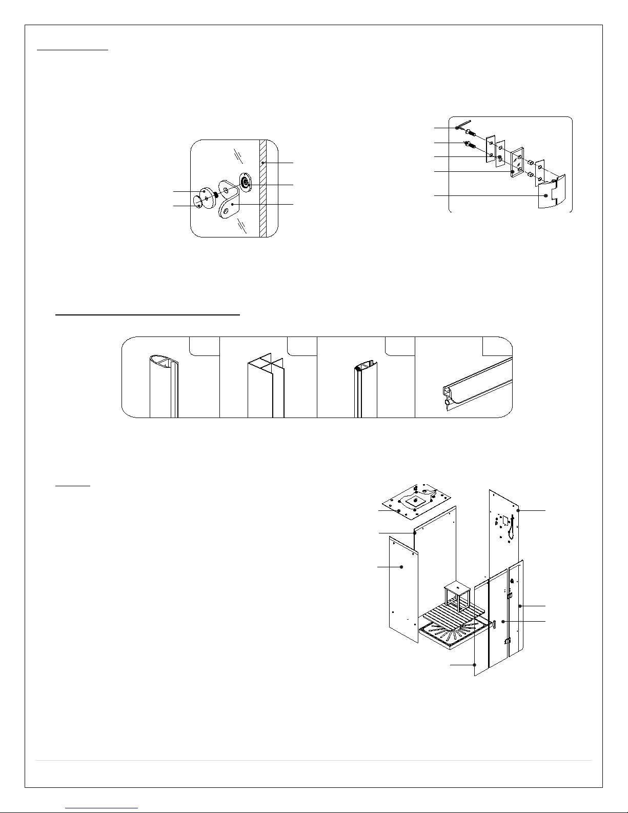
GENERAL INFORMATION
•Connect hot and cold supplies and make all electrical connections just before unit is set into place.
•Units come broken down in panels and are assembled with screws, nuts and bolts on site.
•This unit assembles from the inside for convenience.
•Note: All shower bases are a man made stone composite and may need to be set in mortar for leveling
purposes.
•It is advised to have base onsite before preparing drain location
•Access panel area recommended
•Manufacturer reserves the right to change specs or
features at anytime. Please check to confirm details.
1-866-783-2661
Caulk all needed seams and joints with 100%silicone caulk.
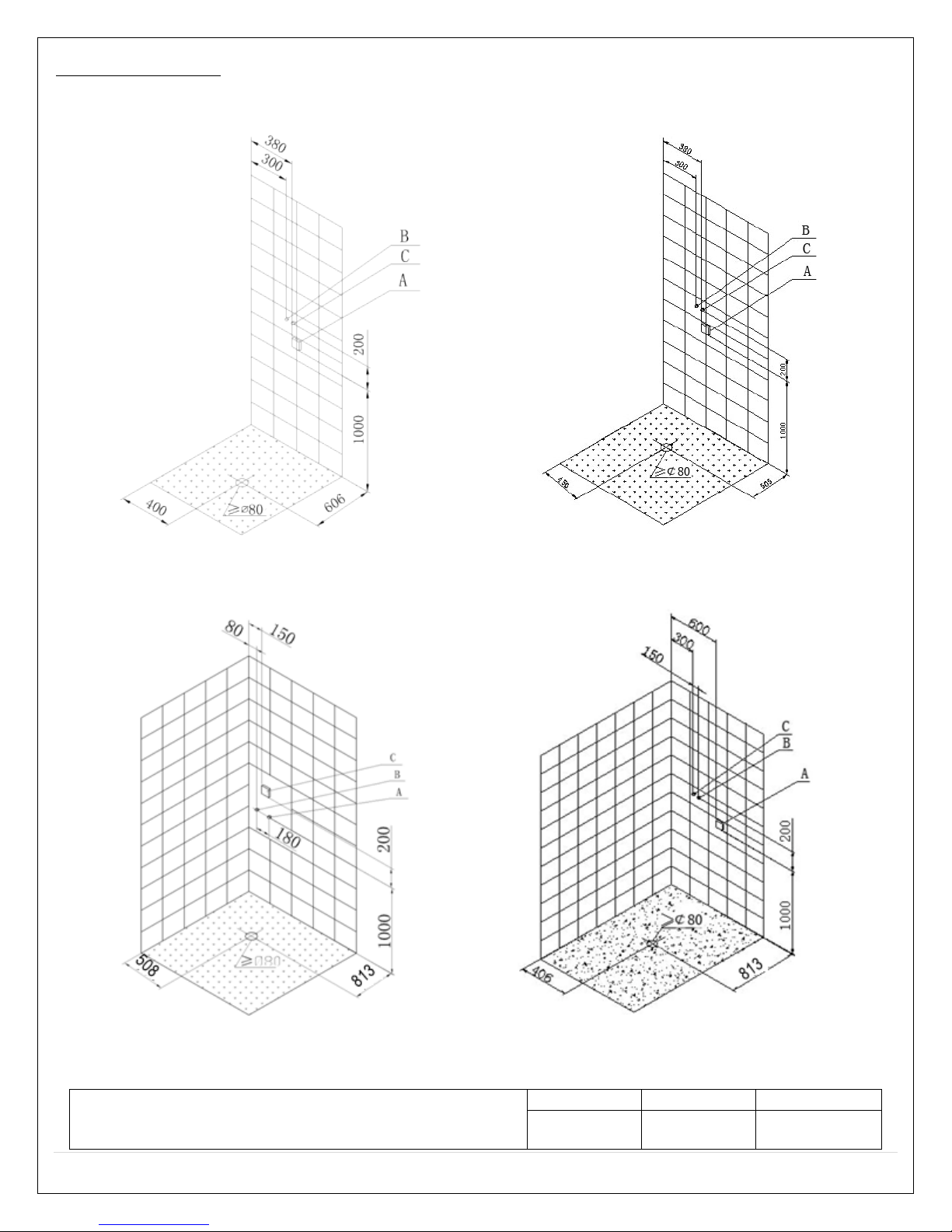
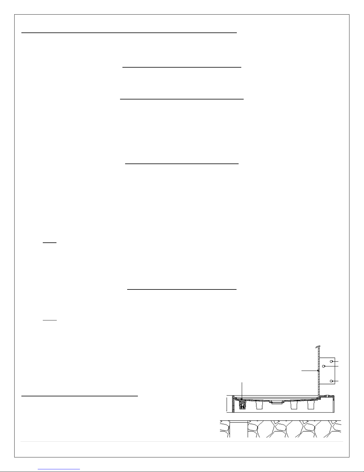
DRAIN INSTALLATION FOR ALL MODELS
For glass steam roomand shower room with 150mm shower tray:
A: Glass A
B: Steam Generator Drain
C: Shower Drain
D: Shower tray