
STARLANE ATHON GPS Manuel utilisateur

ATHON GPS
Installation and operation manual.
Manuale d’installazione e uso.
ATHON GPS is an automatic chrono developed with GPS technology and process
algorithms used in the most advanced airborne systems. Its features make it the most
advanced, complete and easy instrument for all the drivers of:
Go Karts Cars Motorbikes and Scooters.
ATHON GPS è un cronometro automatico basato su tecnologia GPS e algoritmi di
calcolo utilizzati nei più moderni sistemi dell'aviazione. Le sue caratteristiche lo
rendono lo strumento più avanzato, completo e semplice per tutti i piloti di:
Go Kart Auto Moto Scooter.

2

3
Contents
Contenuti
Chapter Capitolo Pag.
Functions Funzioni 4
Introducing the GPS technology introduzione alla tecnologia GPS 4
Installation of ATHON GPS Installazione di ATHON GPS 6
Frontal Panel Pannello frontale 7
Alimentazione Power Supply 8
Connessione alla batteria a 12V del
veicolo Connection with the 12V battery of the vehicle 9
Alimentazione con batterie interne Power supply with internal batteries 9
Collegamento del filo di segnale regime
motore (RPM) Connecting the engine RPM reading wire 10
Multi page menu Menu Multipagina 11
GPS signal acquisition Acquisizione del segnale GPS 12
Setting the Freeze Time Impostazione del tempo di visualizzazione a fine giro 12
Setting the RPM reading parameters Impostazione dei parametri di lettura regime motore 13
Aligning the GPS clock to the local
timezone Allineamento dell’orologio GPS con l’ora locale 14
Setting the LED Bar and the Shift light Impostazione delle barra LED e del Flash di Fuorigiri 15
Selection of the units of measurement Scelta delle unità di misura 15
Learning the Finish Line and
Intermediate positions
Ap
prendimento della linea del Traguardo e degli
Intermedi 16
Storing the coordinates of the Finish line
and Intermediate positions
Memorizzazione delle coordinate di Traguardo ed
Intermedi 17
Loading the track coordinates Richiamare le coordinate di un circuito 18
The “Best Lap” LED Il LED “Best Lap” 18
Analysis of the stored times Analisi dei tempi memorizzati 19
Managing the Hour Meters Gestione dei Contaore 20
Resetting the Hour Meters Azzeramento dei Contaore 21
Checking the memory in use Verifica della memoria utilizzata 22
Memory clearing Cancellazione della memoria 22
Setting Energy saving ad Auto Power OFF
Impostazione del risparmio energetico e
dell’autospegnimento 23
ATHON GPS R / RW and PRO versions Versioni ATHON GPS R / RW e PRO 25
Cleaning the surfaces Pulizia delle superfici 25
Warranty Garanzia 25
Notes Note 25

4
Functions
Funzioni
ATHON GPS carries out the following basic functions:
ATHON GPS svolge le seguenti funzioni base:
GPS Chrono with airborne algorithms.
Cronometro GPS con algoritmi aeronautici.
Double Hour Meter.
Doppio Contaore.
Engines eed indicator.
Contagiri motore.
Calendar.
Calendario.
GPS Tachometer.
Tachimetro GPS.
Clock.
Orologio.
Shift Light.
Flash di Fuorigiri
Several advanced functions are available for the various models of the ATHON GPS range and they are
described here below in the s ecific manual sections.
Diverse funzioni avanzate sono disponibili per i vari modelli della gamma THON GPS e sono illustrate di
seguito nelle specifiche sezioni del manuale.
INTRODUCING THE GPS TECHNO OGY
INTRODUZIONE A A TECNO OGIA GPS
In 1991, the USA o ened the SPS (Standard Positioning System) service, other than PPS (Precision
Positioning System), the military one, to the world. SA (Selective Availability) introducing intentional errors into
satellite signals was ractically brought in.
GPS was created to re lace Transit, i.e. the revious system, when the USA renounced Selective Availability
and made the former system as accurate as the latter and it is su orted by a system of 24 artificial satellites.
Till May 2000, the signal for civilian use was degraded to reduce accuracy u to 100-150 m through Selective
Availability (SA). From then on, signal degradation was disabled by virtue of a decree by Bill Clinton, the
President of the United States, so as to reach the current degree of accuracy that can usually reach levels of
less than 1 m. The models for civilian use are com lete with a device inhibiting o eration at heights and
s eeds above well-defined values in order to avoid its assembly on im rovised missiles.
The EU is lanning to com lete its own network of satellites (Galileo) for civilian ur oses, including GPS. This
roject is of strategic significance since the American network is owned by the USA only and managed by
military authorities who might decide to reduce accuracy or to selectively lock the access to the system. An
investment and a ro erty shared by the States using it are a guarantee of the service continuity, accessibility
and intero erability.
• The navigation system is subdivided into the following com onents:
• An ensemble of 24 satellites
• A network of tracking stations

5
• A com uting station
• Two injection stations
• A GPS receiver
The satellites are arranged on orbits inclined by 55°, com ared to the Equator (this means that they are
unable to cover olar areas), in the sha e of a low-eccentricity elli se. Their height is 20 200 Km. Every single
satellite will emit on the 1.2 and 1.5 Ghz frequencies derived from one single high-stability oscillator. The
ur ose of double frequency is to remove the error due to atmos heric refraction. The e hemeris messages,
each one for the length of two minutes, are emitted on these hase-modulated carrier frequencies. They start
and end at the even whole minutes of the T.M.G. These e hemeris messages contain the time signal and the
orbital arameters of the satellite.
On doing the do ler com utation, the GPS receiver will receive the arameters of the orbit giving rise to the
satellite osition and all the elements necessary to define the osition surface in the s ace are made available.
The operation principle is based on a spheric positioning method. It consists in measuring the time a radio
signal will require to cover the satellite-receiver distance. If you know the exact position of at least 3 satellites
to have a 2D (two-dimensional) position and of at least 4 satellites to have a 3D (three-dimensional) position
as well as the time the signal will require to reach the receiver, you can determine the position of the receiver
in the space. This procedure is referred to as trilateration. It uses distance information only, similarly to
triangulation, but which is also using information on angles.
Nel 1991 gli US aprirono al mondo il servizio con il nome SPS (Standard Positioning System), ma
differenziato da quello militare denominato PPS (Precision Positioning System). In pratica veniva introdotta la
S (Selective vailability) che introduceva nei segnali satellitari degli errori intenzionali.
Il GPS è stato creato a sostituzione del precedente sistema, il Transit, quando gli US hanno rinunciato alla
Selective vailability ed hanno reso il primo sistema accurato quanto il secondo, ed è supportato da un
sistema di 24 satelliti artificiali.
Fino al maggio 2000, il segnale per uso civile veniva degradato per ridurre la precisione attraverso la Selective
vailability (S ), consentendo precisioni nell'ordine di 100-150 m. Da quella data, invece, per decreto del
Presidente degli Stati Uniti Bill Clinton, è stata disabilitata la degradazione del segnale, consentendo la
precisione attuale che usualmente arriva anche a livelli inferiori a 1 m. Nei modelli per uso civile è presente un
dispositivo che inibisce il funzionamento ad altezze e velocità superiori a certi valori, per impedirne il
montaggio su missili improvvisati.
L'UE ha in progetto il completamento di una propria rete di satelliti (Galileo) per scopi civili, fra i quali il GPS.
Questo progetto ha una valenza strategica in quanto la rete americana è proprietà dei soli US e in gestione
ad autorità militari, che potrebbero decidere di ridurre la precisione o bloccare selettivamente l'accesso al
sistema; un investimento e proprietà condivisi dagli Stati utilizzatori sono una garanzia di continuità,
accessibilità e interoperabilità del servizio.
• Il sistema di navigazione si articola nelle seguenti componenti:
• un complesso di 24 satelliti
• una rete di stazioni di tracciamento (tracking station)
• un centro di calcolo (computing station)
• due stazioni di soccorrimento (injection stations)
• un ricevitore GPS
I satelliti sono disposti su orbite inclinate di 55° rispetto al piano equatoriale (quindi non coprono le zone polari)
a forma di ellissi a bassa eccentricità. La loro quota è di 20 200 Km. Ciascun satellite emette sulle frequenze

6
di 1,2 e 1,5 Ghz derivate da un unico oscillatore ad alta stabilità. Lo scopo della doppia frequenza è quello di
eliminare l'errore dovuto alla rifrazione atmosferica. Su queste frequenze portanti, modulate in fase, vengono
emessi i messaggi di effemeride ciascuno della durate di due minuti; essi iniziano e terminano ai minuti pari
interi del T.M.G. Questi messaggi di effemeride contengono il segnale orario e i parametri orbitali del satellite.
In tal modo il ricevitore GPS, mentre effettua il conteggio doppler, riceve i parametri dell'orbita da cui deriva la
posizione del satellite: viene così a disporre di tutti gli elementi necessari a definire nello spazio la superficie di
posizione.
Il principio di funzionamento si basa su un metodo di posizionamento sferico, che consiste nel misurare il
tempo impiegato da un segnale radio a percorrere la distanza satellite-ricevitore. Conoscendo l'esatta
posizione di almeno 3 satelliti per avere una posizione 2D (bidimensionale) e 4 per avere una posizione 3D
(tridimensionale) ed il tempo impiegato dal segnale per giungere al ricevitore, è possibile determinare la
posizione nello spazio del ricevitore stesso. Tale procedimento è chiamato trilaterazione, che utilizza solo
informazioni di distanza, simile alla triangolazione, nella quale però vengono usate anche informazioni
riguardanti gli angoli.
Installation of ATHON GPS
Installazione di ATHON GPS
ATHON GPS is easily installed in the windshield of a Motorbike, on the fork late, on the steering wheel of a
Go Kart, or on the dashboard of a Car.
Fix ATHON GPS with su lied adhesive Dual Lock System or the elastic su ort kit.
ATHON GPS si installa facilmente nel cupolino di una moto, sulla piastra forcella, sul volante di un go Kart, o
sul cruscotto di un’auto.
Fissare ATHON GPS con il sistema Dual Lock a strappo fornito o con il kit di supporti elastici.

7
IMPORTANT: To rotect ATHON GPS against vibrations, never fix it rigidly to the vehicle and make sure it
will never be in contact with any rigid art thereof.
IMPORTANTE: Per proteggere ATHON GPS dalle vibrazioni, non fissarlo mai in modo rigido al veicolo e
controllare che non abbia alcuna parte in contatto con organi rigidi del mezzo.
Front Panel
Pannello Frontale
The LED Bar, the Best La LED, the three blue high ower LEDs of the shift light, the back-lit dis lay and the
4-key key ad are located on the front anel.
Sul Pannello Frontale si trovano la Barra LED, il LED Best Lap, i tre LED Blu ad alta luminosità del Flash di
Fuorigiri, il display retroilluminato e la tastiera a 4 tasti.
Press the key to choose the main screen you wish among the various ones made available for your
Athon GPS model.
Premendo il tasto è possibile scegliere la schermata principale preferita tra le varie disponibili per il
vostro modello di thon GPS.
The “Best La ” LED is a very useful function to immediately give immediate information on a better
erformance without distracting the driver by making him read the dis lay.

8
Il LED “Best Lap” è una funzione molto utile per dare informazioni immediate sul miglioramento della
prestazione senza distrarre il pilota per la lettura del display.
• If the “BEST LAP” LED lights on it means a better time com ared to the revious la .
Il LED “BEST L P” si illumina fisso se viene migliorato il tempo rispetto al giro precedente.
• If the “BEST LAP” LED blinks it means you have just closed your best la time of the session in
rogress.
Il LED “BEST L P” lampeggia se il giro appena concluso è il migliore della sessione in corso.
The “BEST LAP” LED also works for the intermediates if they have been set.
Il LED “BEST L P” funziona anche al passaggio sugli Intermedi se questi sono stati impostati.
Power supply
Alimentazione
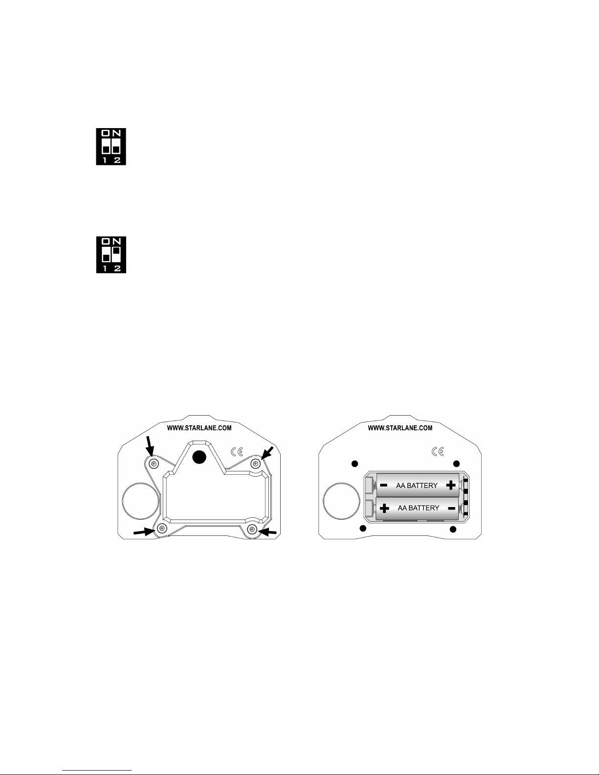
You can su ly Athon GPS by means of a 12V battery of the vehicle or by means of two AA internal batteries.
According to the ty e of ower su ly you choose, you shall set u the DIP SWITCH inside the battery
com artment.
E’ possibile alimentare thon GPS tramite batteria a 12V del veicolo oppure con due batterie interne di tipo
. In funzione del tipo di alimentazione prescelto è necessario impostare il DIP SWITCH che si trova
all’interno del vano batterie.
Important: never keep the batteries inside the instrument if you use the external power supply of the
vehicle.
Non mantenere le batterie all’interno dello strumento se si usa l’alimentazione esterna del veicolo.
9
Connection with the 12V battery of the vehicle
Connessione alla batteria a 12V del veicolo
Turn both cursors of the DIP SWITCH downwards (OFF) to set u the external ower
su ly and the ower on of the device through the ON/OFF key.
Posizionare entrambi i cursori del DIP SWITCH verso il basso (OFF) per impostare
l’alimentazione esterna e l’accensione del dispositivo attraverso il tasto ON/OFF.
Turn cursor 1 of the DIP SWITCH downwards (OFF) and cursor 2 u wards (ON) to set u the external su ly
and the automatic ower on of the device when it is su lied, erfectly suitable for installations connected by
means of a main switch or a ower-on key.
Posizionare il cursore 1 del DIP SWITCH verso il basso (OFF) e il cursore 2 verso l’alto
(ON) per impostare l’alimentazione esterna e l’accensione del dispositivo automatica
quando riceve alimentazione, ideale per installazioni con collegamento sotto interruttore
generale o chiave di accensione.
Connect the ower su ly Red wire with the 12V Positive of the vehicle battery and the Black wire with an
earth oint on the frame or, even better, directly with the Negative of the battery.
Collegare il filo Rosso di alimentazione al Positivo 12V della batteria del veicolo e il filo Nero ad un punto di
massa sul telaio o, meglio ancora, direttamente al Negativo della batteria
Power supply with internal batteries
Alimentazione con batterie interne
ATHON GPS can be su lied by 2 AA batteries (for the ur ose of endurance it is advisable to use min. 2100
mAh rechargeable batteries, also available in su ermarkets). To insert batteries:
ATHON GPS può essere alimentato da 2 batterie tipo (per avere una buona durata sono consigliate
batterie ricaricabili da almeno 2100 m h acquistabili anche nei supermercati), per inserire le batterie:
• Remove the 4 cover screws of the battery com artment and o en the com artment.
• Set the DIP SWITCH to turn cursor 1 u wards (ON) and cursor 2 downwards (OFF)
• Rimuovere le 4 viti del coperchio del vano batterie e aprire il vano.

10
• Impostare il DIP SWITCH con il cursore 1 verso l’alto (ON) e il cursore 2 verso il basso (OFF
• Insert the batteries just as it is shown by the figure, osition the cover and tighten the screws once again.
• Inserire le batterie come indicato in figura, riposizionare il coperchio e riavvitare le viti.
Connecting the engine RPM reading wire
Collegamento del filo di segnale regime motore (RPM)
Option A: Direct electrical connection. (only if you use the ower su ly from the 12V battery of the vehicle)
Opzione A: Collegamento elettrico diretto. (solo se si utilizza l’alimentazione dalla batteria 12V del veicolo)
Connect the atch Black cord (su lied in the ackage) directly with the signal wire (0-5 Volt) of the original
revolution indicator and connect it with the Athon GPS Violet wire.
Collegare il filo Nero di prolunga (fornito nella confezione) direttamente al filo di segnale (0-5Volt) del contagiri
originale e connetterlo al filo Viola di thon GPS.
Attention: the signal of the original speed indicator is not of a 0 5Volt type on some vehicles, but it
directly comes from the power input wire of one of the ignition coils. This connection would damage
the internal Athon GPS circuit.
Attenzione: su alcuni veicoli il segnale del contagiri originale non è di tipo 0 5Volt ma arriva
direttamente dal pilotaggio di potenza di una delle bobine di accensione, tale collegamento
danneggerebbe il circuito interno di Athon GPS.
Option B: Ignition coil Inductive reading (no electrical connection)
Opzione B: Lettura induttiva dalla bobina di accensione (senza connessione elettrica)
In the case of Internal Coils built in the cylinder head wind the ATHON Black wire with at least 8 turns round
the in ut wires of one of the coils (see Picture). If the s eed readout is not correct, increase the number of
turns and check the settings indicated in the aragra h “Setting the RPM reading arameters” in this manual.
If there are unex ected flashes of the shift light or incorrect instantaneous values, check the Black wire to
ensure that it does not receive any interference from the cables of other cylinders, and therefore to make sure
that the wire goes through arts of the chassis far from other coils and, if ossible, it can be cut to the required
length so that it does not receive any undesired signals.In the case of External Coils, just ut the wire in
contact with the high voltage cable of the coil (see Picture).
In caso di Bobine Integrate nella testata motore avvolgere il filo Nero di THON con almeno 8 spire attorno ai
fili di pilotaggio di una delle bobine (vedere Figura). Se la lettura del regime non è corretta, aumentare il
numero delle spire e controllare le impostazioni nel paragrafo “Impostazione dei parametri di lettura regime
motore” nel presente manuale .Se si riscontrano accensioni anomale del Flash di Fuorigiri o valori istantanei
non corretti,controllare che il filo Nero non riceva interferenze dai cavi di altri cilindri, verificare quindi che
percorra parti del telaio lontane da altre bobine e, se possibile, può essere accorciato alla lunghezza
necessaria in modo che non riceva segnali indesiderati. In caso di Bobine Esterne è sufficiente appoggiare il
filo a contatto con il cavo di alta tensione della bobina (vedere Figura).
Table des matières


