Standard Horizon FF525 Manuel utilisateur

Page 4
This guide relates to the following GPS CHART PLOTTERS:
CP180,CP180i,CP190i,CP300,CP300i,CPV350,CP390i,CP500,CP590andCPV550.
For older GPS Chart Plotters, the manual is available for download at
www.standardhorizon.comorbycontactingMarineProductSupportat800-
767-2450 ext 6800.
FCC Compliance Statement
Thisdevice complieswith Part15 ofthe FCClimits forClass Adigital devices.This
equipment generates, uses and can radiate radio frequency energy and, if not
installedorusedinaccordancewiththeinstructionsmaycauseharmfulinterference
with radio communications.
Thereis no guarantee that interference will notoccur ina particularinstance. Ifthis
equipment does cause harmful interference to other equipment, try to correct the
problem by relocating the equipment.
Consult an authorized STANDARD HORIZON dealer or other qualified service
technician if the problem cannot be corrected. Operation is subject to the following
conditions: (1) This device cannot cause harmful interference, and (2) this device
must accept any interference received, including interference that may cause
undesiredoperation.
CAUTION
- The FF525 contains dangerous high-voltage circuits which only experienced
technicians can handle.
- STANDARD HORIZON will not be liable for errors contained herein, or for
incidentalorconsequentialdamagesinconnectionwiththeperformanceoruseof
this material.
- Because we frequently update our software and applications, the pictures shown
through this Owner’s Manual may be slightly different from what you see.
WARNING
- When plugging in or unplugging a transducer to the FF525 make sure power is
turned off.
Copyright 2012. YAESU MUSEN CO., LTD. All rights reserved. Printed in Italy.
No portion of this manual may be reproduced without the permission of YAESU MUSEN CO., LTD.
CODE: Operation Manual - Issue C - 100212e
WARNING
- ThisOwner'ManualisforGPSChartPlotterswithsoftwareversion16.50andlater.

CP and FF525 Operation Manual Page 5
TABLE OF CONTENTS
1. INTRODUCTION ...................................................................................................................7
1.0 CONVENTIONS USED.....................................................................................7
1.1 CHART PLOTTERS..........................................................................................7
1.2 GENERAL INFORMATION............................................................................... 7
Product Support Inquiries ................................................................................. 7
2. CONNECTING THE FF525................................................................................................... 8
2.0 CP180/CP180i/CP190i .....................................................................................8
2.1 CP300/CP300i/CP390i .....................................................................................9
2.2 CPV350 .............................................................................................................9
2.3 CP500/CP590 .................................................................................................10
2.4 CPV550 ...........................................................................................................10
2.5 SOFTWARE SETUP ...................................................................................... 11
3. OPERATION............................................................................................................... 12
3.0 UNDERSTANDING THE FISH FINDER PAGE ............................................. 12
3.1 UNDERSTANDING THE FISH FINDER DISPLAY ........................................14
3.2 DISPLAYING THE FISH FINDER PAGE .......................................................14
3.2.0 Auto Full Page....................................................................................15
3.2.1 200 kHz Full, 50 kHz Full and 50&200kHz Display Pages................15
3.2.2 200 kHz and 50 kHz Zoom Pages .....................................................16
3.2.3 200 kHz and 50 kHz Fish/Chart Pages .............................................16
3.2.3.0 Focus on FISH/CHART Page ................................................16
3.2.4 Radar Pages (except CP180/CP180i/CP190i) ..................................17
3.2.4.0 FISH/RADAR/CHART Page ..................................................17
3.2.4.1 RADAR COMBO Page ..........................................................17
3.2.4.2 Focus Soft Key.......................................................................17
3.3 SOFT KEY OPERATION (except CP180/CP180i/CP190i) ...........................18
3.3.1 Customizing the Soft Keys................................................................. 18
4. FISH FINDER SETUP MENU ....................................................................................19
4.0 FISH FINDER COLOR.................................................................................... 19
4.1 PRESETS .......................................................................................................19
4.2 FREQUENCY..................................................................................................20
4.3 GAIN MODE....................................................................................................20
4.3.0 Auto Mode ..........................................................................................21
4.3.1 Manual Mode...................................................................................... 21
4.4 RANGE MENU ................................................................................................ 21
4.4.0 Range Mode ....................................................................................... 21
4.4.1 Depth ..................................................................................................21
4.4.2 Shift ....................................................................................................21
4.5 INTERFERENCE REJECTION ......................................................................22
4.6 SENSITIVITY MENU ......................................................................................22
4.6.0 Gain ....................................................................................................22
4.6.1 STC (Sensitivity Time Control) ..........................................................23
4.6.2 Surface Noise Filter............................................................................24
4.7 DISPLAY SETUP ............................................................................................24

Page 6
4.7.0 Color Settings..................................................................................... 25
4.7.1 Scrolling Speed ..................................................................................25
4.7.2 White Line .......................................................................................... 25
4.7.3 Fish Symbols...................................................................................... 25
4.7.4 A-Scope..............................................................................................25
4.7.5 Water Temperature ............................................................................ 25
4.8 TRANSDUCER SETUP ..................................................................................26
4.8.0 Keel Offset .........................................................................................26
4.8.1 Calibrate Water Speed....................................................................... 26
4.8.2 Calibrate Water Temp........................................................................26
4.8.3 Calibrate Aux Temp ...........................................................................26
4.8.4 Set Defaults........................................................................................ 26
4.9 ALARMS.......................................................................................................... 26
4.9.0 Shallow Water ....................................................................................27
4.9.1 Deep Water ........................................................................................27
4.9.2 Fish..................................................................................................... 27
4.9.3 Temperature Upper............................................................................27
4.9.4 Temperature Lower ............................................................................27
4.9.5 Temperature Rate ..............................................................................27
4.10 SAVE SETTINGS TO USER C-CARD ...........................................................27
4.11 LOAD SETTINGS FROM USER C-CARD ..................................................... 28
4.12 RESTORE CURRENT PRESET DEFAULTS ................................................28
5. OPERATION TIPS .....................................................................................................29
INDEX ......................................................................................................................................32

CP and FF525 Operation Manual Page 7
1. INTRODUCTION
This manual provides basic information in becoming familiar with the advanced functions of the
FF525 before you start using it combined with the STANDARD HORIZON GPS Chart Plotters.
1.0 CONVENTIONS USED
Please refer to the legend below:
[MENU] If you see brackets around a bold and capital letter word this refers to a key press.
[CHART]If you see brackets around a bold andsmallcapitalletterwordthis refers to a Soft Key
press.
GENERAL SETUP Whenaword(s)isinboldcapitallettersandunderlined,thisreferstoamenuselection
item.
1.1 CHART PLOTTERS
Any menu operation and functions activation in this Operation Manual is related to the
followingChart Plottermodelswithsoftwarecapableto operatewithFF525.Wheneveritis
necessary, a note has been inserted for those models with operational differences.
·CP180
·CP180i
·CP190i
·CP300
·CP300i
·CP390i
·CPV350
·CP500
·CP590
·CPV550
1.2 GENERAL INFORMATION
PRODUCT SUPPORT INQUIRIES
If you have any questions or comments:
·USA customers should contact STANDARD HORIZON on 714-827-7600 or by email
·UK customers should contact STANDARD HORIZON on 01962 866667 or email
·European customers should contact their local dealer or distributor for support.
Page 8
2. CONNECTING THE FF525
The FF525 must be properly installed according the following instructions to get the best
possible performance. For more information on installation please see the FF525
InstallationManual.
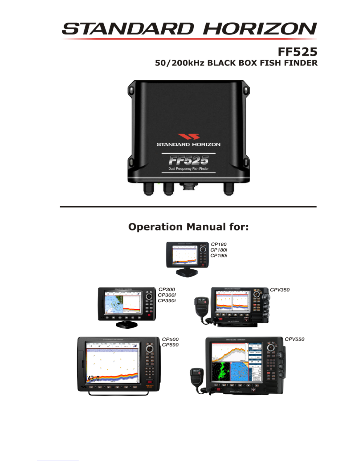
2.0 CP180/CP180i/CP190i
FF525 Fish Finder
Dual Frequency Fish Finder
Accessory
cable
Black
Red
Green
Gray
Blue
Brown
White
Yellow
NMEA Common
Port1 Input
Port1 Output
Port2 Input
Port2 Output
Port3 Output
Note:
Gray and White wires should not be connected
to other devices when the FF525 is connected.
Fuse
Switch
+
BATTERY
-
CP and FF525 Operation Manual Page 9
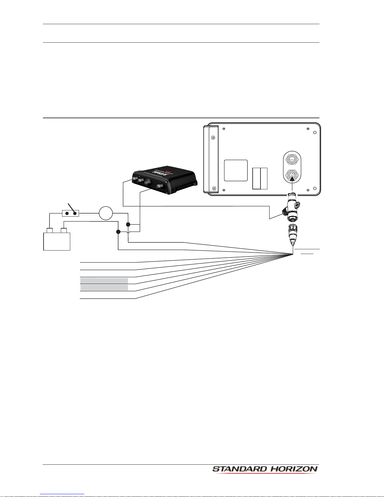
2.1 CP300/CP300i/CP390i
Fuse
Switch
+
BATTERY
-
Accessory
cable
Black
Red
Green
Gray
Blue
Brown
White
Yellow
NMEA Common
Port1 Input
Port1 Output
Port2 Input
Port2 Output
Port3 Output
Note:
Gray and White wires should not be connected
to other devices when the FF525 is connected.
FF525 Fish Finder
DualFrequencyFishFinder
2.2 CPV350
Black
Red
Fuse
Switch
+
BATTERY
-
Accessory cable
Black
Red
Green
Gray
Blue
Brown
White
Yellow
NMEA Common
Port1 Input
Port1 Output
Port2 Input
Port2 Output
Port3 Output
Note:
Gray and White wires should not be connected
to other devices when the FF525 is connected.
FF525 Fish Finder
Dual Frequency Fish Finder
Page 10
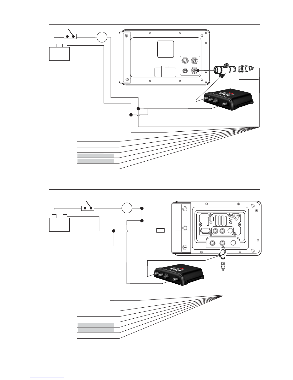
2.3 CP500/CP590
Note:
Gray and White wires should not be connected
to other devices when the FF525 is connected.
Note:
The Tee cable is supplied
with the FF525.
If the F 525 is not connected,
plug the Accessory cable
directly into the PWR ACC 1
connector.
F
GPS ANT
PWR & ACC 1
ACC 2
VIDEO OUT VIDEO IN 1 VIDEO IN 2
PWR ACC 1 Cable
Black
Fuse
Switch
Red
+
BATTERY
-
Green
Gray
Blue
Brown
White
Yellow
NMEA Common
Port1 Input
Port1 Output
Port2 Input
Port2 Output
Port3 Output
FF525 Fish Finder
DualF
requencyFishFinder
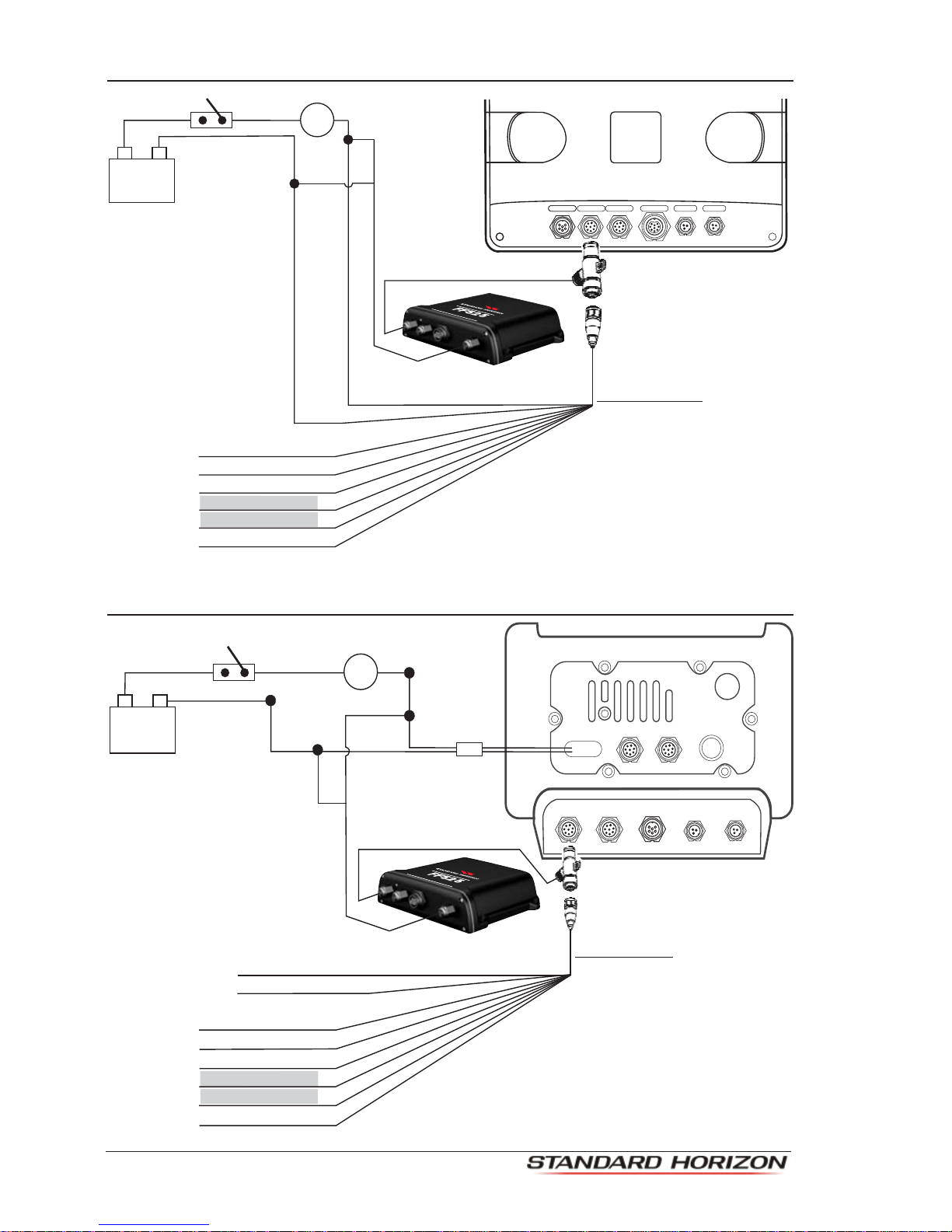
2.4 CPV550
VIDEO 1GPSAUX
1 RAM 2
I/O VIDEO 2
Black
Red
Fuse
Switch
+
BATTERY
-
Green
Gray
Blue
Brown
White
Yellow
NMEA Common
Port1 Input
Port1 Output
Port2 Input
Port2 Output
Port3 Output
Note:
Gray and White wires should not be connected
to other devices when the FF525 is connected.
Accessory cable
Black (no connection)
Red (no connection)
FF525 Fish Finder
DualFrequencyFishFinder

CP and FF525 Operation Manual Page 11
2.5 SOFTWARE SETUP
NOTE
Onsoftwareversion16.00.00Rorlater,port 2 of the GPS Chart Plotter has been set to FF525 by
default. If the software in the GPS Chart Plotter is earlier than 16.00.00R, follow the steps below.
1. From the Chart page, press [MENU], move the ShuttlePoint knob to highlight SETUP
MENU and press [ENT].
2. MovetheShuttlePointknobtohighlightADVANCED SETUPandpress[ENT]ormove
the ShuttlePoint knob to the right.
3. Move the ShuttlePoint knob to highlight IN/OUT CONNECTIONS and press [ENT] or
move the ShuttlePoint knob to the right.
4. Move the ShuttlePoint knob to highlight PORT 2 INPUT and press [ENT] or move the
ShuttlePoint knob to the right.
5. Movethe ShuttlePointknobup/downtoselect FISH FINDER and press[ENT]ormove
the ShuttlePoint knob to the right.
6. Press [CLR] or move the ShuttlePoint knob to the left until the Chart Page is shown.
Page 12
3. OPERATION
3.0 UNDERSTANDING THE FISH FINDER PAGE
The display on STANDARD HORIZON GPS Chart Plotters shows a history of time of the
echoes received by the transducer. The STANDARD HORIZON GPS Chart Plotters have
a menu that allows adjustments to receiver sensitivity, depth range and scrolling speed of
the Fish Finder display.
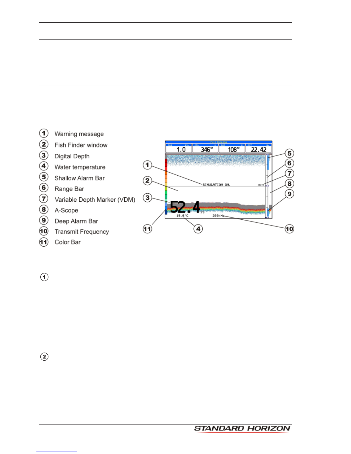
Figure 3.0 - The Fish Finder page
The following is a brief description of terms listed in the previous Figure:
WarningMessage
Flashing label that is turned On when the echo sounder is in Simulation mode.
The following is the list of the warning messages:
·SHALLOW WATER ALARM
·DEEP WATER ALARM
·HIGH WATER TEMP ALARM
·LOW WATER TEMP ALARM
·WATER TEMP RATE ALARM
·FISH SPOT
·NO DATA, problem with connection between CP and Fish Finder Tee Cable
Fish Finder window
Graphic presentation of sonar soundings recorded as a continuous bottom scrolling
across the screen from right to left. Such recordings represent the image of the water
beneathyourboat, items appearasthey passunderyour transducer; theitemson the
rightsideofthescreenareclosertoyouthanthoseontheleft.Thecorrectinterpretation
oftheFishFinderpageallowsretrievingusefulinformationaboutwhatisundertheboat.
Autres manuels pour FF525
4
Ce manuel convient aux modèles suivants
10
Table des matières
Autres manuels Standard Horizon Sondeur de pêche

Standard Horizon
Standard Horizon CP190i Manuel utilisateur

Standard Horizon
Standard Horizon CPF180I Manuel utilisateur

Standard Horizon
Standard Horizon CPF180I Manuel utilisateur

Standard Horizon
Standard Horizon CP1000C Instructions d'installation et d'utilisation

Standard Horizon
Standard Horizon CPF390i Manuel utilisateur

Standard Horizon
Standard Horizon FF520 Manuel utilisateur

Standard Horizon
Standard Horizon FF520 Manuel utilisateur

Standard Horizon
Standard Horizon CP1000C Manuel utilisateur

Standard Horizon
Standard Horizon FF520 Mode d'emploi

Standard Horizon
Standard Horizon FF525 Manuel utilisateur


