Stage Accompany DS20 Series Manuel utilisateur
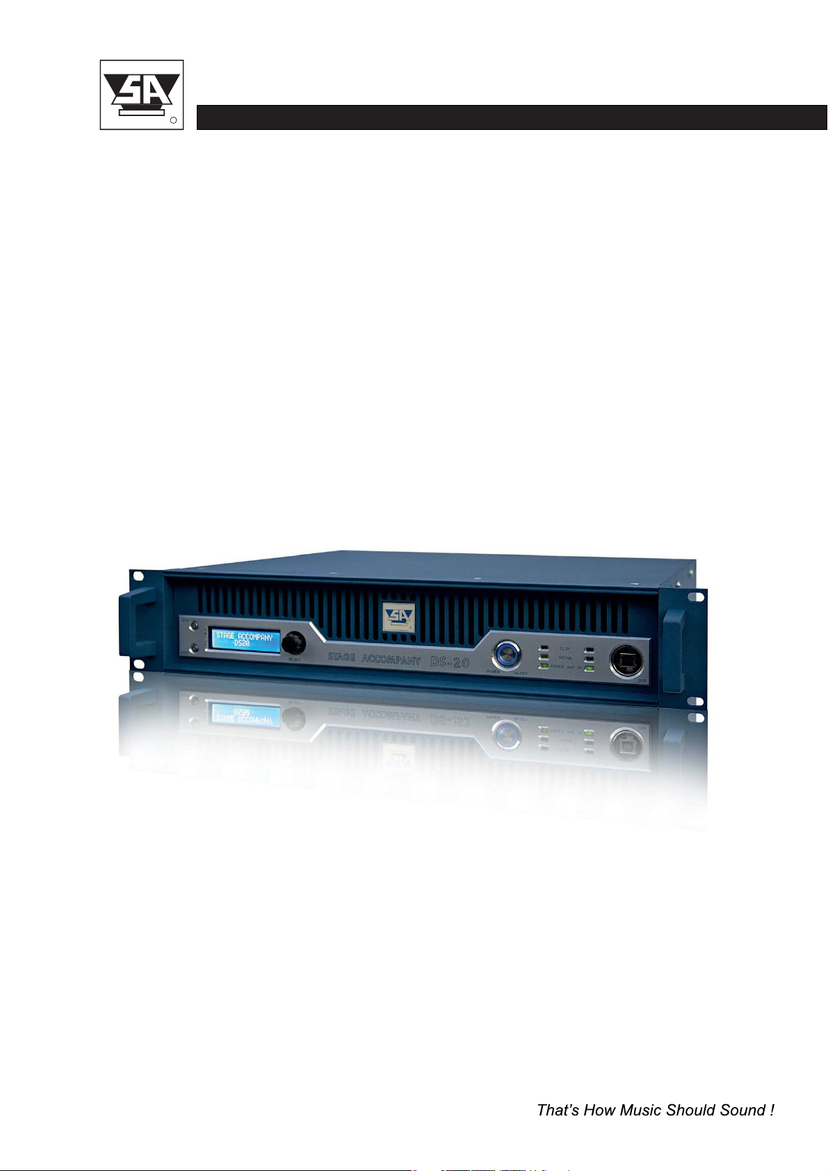
DIGITAL SERIES DS20
User Manual
Version 1.2
Digital Power Amplifier
stage accompany
R
DS20 USER MANUAL

Published by:
Stage Accompany
Training & Documentation
Haven 28
2984 BR Ridderkerk, The Netherlands
Copyright © 2016 by Stage Accompany
All rights reserved. No part of this manual may be reproduced or transmitted in any form or by
any means, electronically or mechanical, without written permission from Stage Accompany,
except for the inclusion of brief quotations in a review.
First printing, October 2016
Printed in The Netherlands
This manual is intended to provide information about the Stage Accompany DS20. Every effort
has been made to make this manual complete and as accurate as possible. However no
warranty of suitability, purpose, or fitness is implied. The information is provided on an “as-is”
basis. Stage Accompany shall have neither liability nor responsibility to any person or identity
with respect to any loss or damages in connection with or arising from the information
contained in this manual.
Stage Accompany reserves the right to alter specifications without prior notice.
stage accompany
R
DS20 USER MANUAL

stage accompany
R
DS20 USER MANUAL
Table of Contents
Quick Introduction to the DS20
Introduction
Connections
Operation
Stage Control
Recommendations
Technical Specifications
Warranty
Overview

Table Of Contents
1 Quick Introduction to the DS20 ................................. 1-1
2 Introduction ................................................. 2-1
3 Connection of the DS20 ....................................... 3-1
3.1 Mains Power Connection ................................... 3-1
3.2 Audio Connections ........................................ 3-4
3.3 Loudspeaker Connections .................................. 3-5
4 Operation ................................................... 4-1
4.1 System check ............................................ 4-1
4.2 Input Setup
4.3 Output Setup
.............................................. 4-1
............................................ 4-5
4.2.1
4.3.1
4.2.2
4.3.2
4.2.3
4.3.3
4.2.4
4.3.4
4.2.5
4.3.5
4.2.6
4.3.6
4.2.7
4.3.7
4.2.8
4.3.8
4.2.9
4.3.9
Gain
Gain
Input Selection
Delay
Delay
Low Pass Filter
Low Pass Filter
High Pass Filter
High Pass Filter
Parametric Equalizer (PEQ)
Parametric Equalizer (PEQ)
Compressor
Compressor
Limiter
Limiter
Channel Link
Phase Inverse
Channel Link
................................................ 4-2
................................................ 4-5
........................................ 4-2
............................................... 4-2
............................................... 4-5
........................................ 4-2
........................................ 4-5
....................................... 4-3
....................................... 4-6
.............................. 4-3
.............................. 4-6
.......................................... 4-4
.......................................... 4-7
.............................................. 4-4
.............................................. 4-7
......................................... 4-4
......................................... 4-7
......................................... 4-8
TABLE OF CONTENTS
stage accompany
R
DS20 USER MANUAL

TABLE OF CONTENTS
stage accompany
R
DS20 USER MANUAL
4.4 System Menu
4.5 Indicators
5.1 Getting started
5.2 Installation instructions
5.3 Start communication
5.4 Quick configuration
5.5 Main Window
5.6 X-over window
5.7 Input Window
5.8 Output window
5.9 Compressor window
............................................ 4-8
............................................ 4-8
........................................... 5-1
..................................... 5-1
....................................... 5-2
........................................ 5-4
............................................ 5-4
........................................... 5-5
............................................ 5-6
........................................... 5-7
........................................ 5-8
4.4.1
4.4.2
4.4.3
4.4.4
Load Preset
Save Preset
Access Level
Version information
.......................................... 4-8
.......................................... 4-8
......................................... 4-9
.................................... 4-9
5 Stage Control ................................................ 5-1
6 Recommendations for Optimum Use............................. 6-1
7 Technical Specifications ....................................... 7-1
8 Warranty .................................................... 8-1
9 Overview.................................................... 9-1

Quick Introduction to the DS20
Thank you for choosing a Stage Accompany Power Amplifier. Making this choice has guaran-
1
teed you many years of troublefree amplification.
If you have to start using the DS20 straight away and do
not have the time to read the complete
manual, make sure that you at least read the following:
•
•
•
•
•
Ensure that you have a reliable, well earthed power source. The required current for
the DS20 can be found in the table in paragraph 3.1.
Connect the DS20 to your signal sources via the <INPUT> connectors. Connect this
amplifier to other units via the <LINK> outputs using short signal leads. Connect your
single signal source to the channel 1 input if you use the DS20
in
dedicated active presets.
Never make connections to the amplifier or to any preceding equipment with the ampli-
fier switched on!
Switch the DS20
on using the <POWER ON/OFF> switch.
Select the desired preset and input sensitivity by means of the <SELECT ROTATOR >.
The DS20 is now ready for use.
QUICK INTRODUCTION
stage accompany
R
DS20 USER MANUAL
1-1

2 Introduction
The Stage Accompany DS20 is a dual channel, digital power amplifier and comprimises the
following components:
•
•
•
•
•
•
•
•
•
•
•
•
Balanced input stages.
Two digital amplifiers wich deliver each 440W into 8 ohms, 700W into 4 ohms and
64-bit 96kHz high quality DSP controller
1200W into 2 ohms.
Advanced protection circuits.
The audio inputs and link outputs are connected internally without electronics. This is done to
prevent any loss of sound quality. With an input impedance of 25 kohms, it is posible to connect
a maximum of 30 DS20 amplifiers to a 600 ohms source like a mixing console. If more than
30 units need to be connected to a single source, a seperate signal driver must be used.
The DS20 is protected against the connection of speaker impedances less than 2 ohms or even
short circuiting of the output. In this fault condition the power supply lines to the amplifier
module will be interrupted.
The DS20 has a number of features, including:
Class D operation.
Variable speed DC fan.
Switched mode power supply.
Dual auto-negotiation RJ45 ports.
DSP processing.
Two channel AES/EBU input.
Soft start to reduce power on inrush current.
Temperature, DC, HF and short circuit protection.
INTRODUCTION
stage accompany
R
DS20 USER MANUAL
2-1

Soft Start
The soft start circuit is active when the DS20 is turned on. The mains inrush current, which
normally is in excess of 60 A is limited to a safe value. However, take care not to switch on
too many DS20 amplifiers at the same time, or you risk that the main fuses of your distribution
may trip.
Temperature, DC, HF and Short Circuit Protection
The amplifier and the loudspeakers are protected against all possible damages.
INTRODUCTION
stage accompany
R
DS20 USER MANUAL
2-2
DSP processing
Switched mode power supply
Class D operation
Two channel AES/EBU input
Dual auto-negotiation RJ45 ports
The built in DSP module is a high quality four input, two output DSP processor with all the
The amplifier stages are individual powered by a low weight high efficiency high power audio
The high performance class D output stages features a flat frequency response irrespective
Two XLR-3 AES/EBU connectors for input and buffered output are mounted at the rear.
An internal high performance 10/100Mbps Ethernet switch module provides a simple network
neccessary features for a professional amplifier. The unit features two analogue and one two
SMPS, optimized from the first phase of design to final impletation to realize the low EMI signature
of load impedance, nearly frequency-independent distortion behaviour and very low radiated and
connection to your workgroup or a server.
channel AES/EBU inputs with full configuration and real-time monitoring via PC controlled by
Ethernet and USB interface.
required of the most demanding audio applications.
conducted EMI.
DC fan
The built in DC fan has a continuous variable speed. Its control circuit monitors the temperature
of the output devices and the temperature of the power supply. The speed of the fan is calculated
out of this information. This system ensures that the fan always runs at optimum speed and
thus produces less noise.

3 Connections
Only three connections need to be made: mains power, audio input signals, and loudspeaker
leads. Do not make any connections to the amplifier or to any preceding equipment with the
amplifier switched on!
3.1 Mains Power Connection
voltage is configured at the factory according to standard used in the country of destination. The
The DS20 is internally selectable for 110-120/220-240V 50/60Hz mains voltage. The mains
exact voltages are stated at the rear of the amplifier. Switching between mains voltages has to
done by an authorised Stage Accompany service centre. Connecting to the wrong voltage is
dangerous and may damage the amplifier. Always ensure that you use a correctly grounded
power supply. If more than one DS20 is to be used, it is advisable to connect each one
separately to the nearest mains supply in stead of connecting several DS20s using an adapter
block (see figure 3-1).
Mains
Supply
Mains
Supply
DS20
DS20
DS20
DS20
DS20
DS20
OK
Figure 3-1 DS20 connections to the mains supply.
stage accompany
R
DS20 USER MANUAL
3-1
CONNECTIONS
This will prevent unnecessary power loss in the mains cables. If circumstances do not allow
this, it is advisable to connect the adapter block directly to the power supply using a short cable
and then connect the individual DS20s to it using longer leads. Although this method is not
ideal, it does limit power loss as much as possible.
Ultimately, it is possible to place the adapter block near the DS20s, but if a great deal of power
is required from the unit, the final current provided is far from optimum: loss of current leads to
unrecoverable loss of output power and therefore sound pressure.
Warning :
Always disconnect the DS20 from the power supply before operating on the fuse holders!
Replace a blown fuse only with a new one of the same type and value!
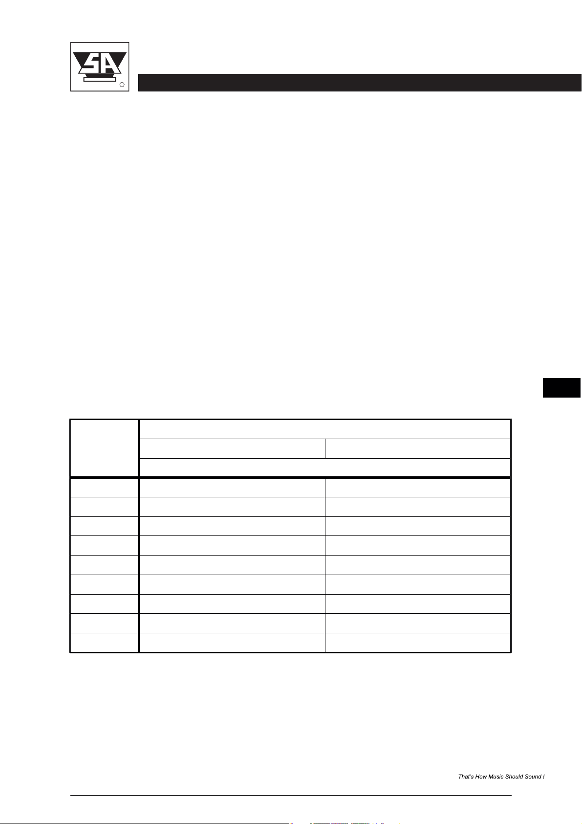
Current Table
Below, the current consumption of the DS20 is tabulated for two selectable mains voltages.
The power consumption shown applies 1/8 of maximum output power pink noise in 2 ohms, wich
is representative for typical music program with occasional clipping. If your speaker system has
an impedance of 4 or 8 ohms you may multiply the currents by 0.5 or 0.25.
The mains voltage may NOT deviate more than -20 % to +10 % of the nominal value. The
proportional mains voltage cable loss may not exceed 10 %. The following formula may be used
to calculate the maximum mains cable length in meters for 220-240 V models:
No. DS20s
Mains Voltage (V)
110-120 220-240
Current Consumption (A)
Table 3-1 Current consumption as a function of the mains voltage at 1/8 of maximum
output power with pink noise in 2 ohms.
stage accompany
R
DS20 USER MANUAL
3-2
1
2
3
4
5
6
7
8
9
8
16
24
36
40
48
56
64
72
4
8
12
18
20
24
28
32
36
CONNECTIONS
Ce manuel convient aux modèles suivants
1
Table des matières
Autres manuels Stage Accompany Amplificateur


