ST VL53L8CX Manuel utilisateur

Introduction
The purpose of this user manual is to explain how to handle the VL53L8X Time-of-Flight (ToF) sensor, using the ultra lite driver
(ULD) API. It describes the main functions to program the device, the calibrations, and the output results.
Based on ST's FlightSense technology, the VL53L8CX incorporates an efficient metasurface lens (DOE) placed on the laser
emitter enabling the projection of a 45° x 45° square FoV onto the scene.
Its multizone capability provides a matrix of 8x8 zones (64 zones) and can work at fast speeds (60 Hz) up to 400 cm.
Thanks to the autonomous mode with programmable distance threshold, the VL53L8CX is perfect for any application requiring
low-power user detection. ST's patented algorithms and innovative module construction allow the VL53L8CX to detect, in each
zone, multiple objects within the FoV with depth understanding. ST histogram algorithms ensure cover glass crosstalk immunity
beyond 60 cm.
Like all Time-of-Flight (ToF) sensors based on ST's FlightSense technology, the VL53L8CX records, in each zone, an absolute
distance regardless of the target color and reflectance.
Housed in a miniature reflowable package that integrates a SPAD array, the VL53L8CX achieves the best ranging performance
in various ambient lighting conditions, and for a wide range of cover glass materials.
All of ST's ToF sensors integrate a VCSEL that emits a fully invisible 940 nm IR light, which is totally safe for the eyes (Class 1
certification).
Figure 1. VL53L8CX sensor module
References
VL53L8CX datasheet (DS14161).
A guide for using the VL53L8CX, low-power, high-performance Time-of-Flight
multizone ranging sensor
UM3109
User manual
UM3109 - Rev 1 - January 2023
For further information contact your local STMicroelectronics sales office.
www.st.com
1Acronyms and abbreviations
Acronym/abbreviation Definition
DOE diffractive optical element
FoV field of view
I2C inter-integrated circuit (serial bus)
Kcps/SPAD Kilo-count per second per spad (unit used to quantify the
number of photons into the SPAD array)
RAM random access memory
SCL serial clock line
SDA serial data
SPAD single photon avalanche diode
ToF Time-of-Flight
ULD ultra lite driver
VCSEL vertical cavity surface emitting diode
Xtalk crosstalk
UM3109
Acronyms and abbreviations
UM3109 - Rev 1 page 2/20

2Functional description
2.1 System overview
The VL53L8CX system is composed of a hardware module and the ultra lite driver software (VL53L8CX ULD)
running on a host (see figure below). The hardware module contains the ToF sensor. STMicroelectronics delivers
the software driver, which is referred to in this document as "the driver". This document describes the functions of
the driver, which are accessible to the host. These functions control the sensor and get the ranging data.
Figure 2. VL53L8CX system overview
2.2 Effective orientation
The module includes a lens over the RX aperture, which flips (horizontally and vertically) the captured image of
the target. Consequently, the zone identified as zone 0, in the bottom left of the SPAD array, is illuminated by a
target located at the top right-hand side of the scene.
Figure 3. VL53L8CX effective orientation
UM3109
Functional description
UM3109 - Rev 1 page 3/20

2.3 Schematics and I2C/SPI configuration
The communication between driver and firmware is handled by the I2C or SPI. The maximum capability of the I2C
is 1 MHz, and the maximum capability of the SPI is 20 MHz. The implementation of each communication protocol
requires pull ups as described into the VL53L8CX datasheet.
The VL53L8CX device has a default I2C address of 0x52. However, it is possible to change the default address
to avoid conflicts with other devices, or to facilitate adding multiple VL53L8CX modules to the system for a greater
system FoV. The I2C address can be changed using the vl53l8cx_set_i2c_address() function. To use the SPI, the
multisensor is wired using an independant slave configuration (the NCS pin).
Figure 4. Multiple sensors on I2C bus
UM3109
Schematics and I2C/SPI configuration
UM3109 - Rev 1 page 4/20

Figure 5. Multiple sensors on SPI
To allow a device to have its I2C address changed without affecting others on the I2C bus, it is important to
disable the I2C communication of the devices not being changed. The procedure is as follows:
1. Power up the system as normal.
2. Pull down the LPn pin of the device that will not have its address changed.
3. Pull up the LPn pin of the device that has the I2C address changed.
4. Program the I2C address to the device using function set_i2c_address() function.
5. Pull up the LPn pin of the device not being reprogrammed.
All devices should now be available on the I2C bus. Repeat the above steps for all the devices in the system that
require a new I2C address.
UM3109
Schematics and I2C/SPI configuration
UM3109 - Rev 1 page 5/20

3Package content and data flow
3.1 Driver architecture and content
The VL53L8CX ULD package is composed of four folders. The driver is located in the folder /
VL53L8CX_ULD_API.
The driver is composed of mandatory and optional files. Optional files are plugins used to extend ULD features.
Each plugin starts with the word "vl53l8cx_plugin" (e.g vl53l8cx_plugin_xtalk.h). If the user does not want
the proposed plugins, they can be removed without impacting the other driver features. The following figure
represents the mandatory files and the optional plugins.
Figure 6. Driver architecture
The user also needs to implement two files located in the /Platform folder. The proposed platform is an empty
shell, and must be filled with dedicated functions.
Note: Platform.h file contains mandatory macros to use the ULD. All the file content is mandatory to correctly use the
ULD.
UM3109
Package content and data flow
UM3109 - Rev 1 page 6/20

3.2 Calibration flow
Crosstalk (Xtalk) is defined as the amount of signal received on the SPAD array, which is due to VCSEL light
reflection inside the protective window (cover glass) added on top of the module. The VL53L8CX module is
self-calibrated, and can be used without any additional calibration.
Xtalk calibration may be required if the module is protected by a cover glass. The VL53L8CX is immune to
Xtalk beyond 60 cm thanks to a histogram algorithm. However, at short distances below 60 cm, Xtalk can be
larger than the actual returned signal. This gives a false target reading or makes targets appear closer than they
really are. All Xtalk calibration functions are included in a Xtalk plugin (optional). The user needs to use the file
‘vl53l8cx_plugin_xtalk’.
The Xtalk can be calibrated once, and data can be saved so it can be re-used later. A target at fixed distance, with
a known reflectance is required. The minimum distance required is 600 mm, and the target must cover the whole
FoV. Depending on the setup, the user can modify settings in order to adapt the Xtalk calibration, as proposed in
the following table.
Table 1. Available settings for calibration
Setting Min Proposed by
STMicroelectronics Max
Distance [mm] 600 600 3000
Number of samples 1 4 16
Reflectance [%] 1 3 99
Note: Increasing the number of samples increases the accuracy, but it also increases the time for calibration. The time
relative to the number of samples is linear, and values follow the approximate timeout:
• 1 sample ≈ 1 second
• 4 samples ≈ 2.5 seconds
• 16 samples ≈ 8.5 seconds
The calibration is performed using the function vl53l8cx_calibrate_xtalk(). This function can be used at any time.
However, the sensor must be initialized first. The following figure represents the Xtalk calibration flow.
Figure 7. Xtalk calibration flow
UM3109
Calibration flow
UM3109 - Rev 1 page 7/20

3.3 Ranging flow
The following figure represents the ranging flow used to get measurements. Xtalk calibration and optional function
calls must be used before starting the ranging session. The get/set functions cannot be used during a ranging
session, and 'on-the-fly' programming is not supported.
Figure 8. Ranging flow using VL53L8CX
UM3109
Ranging flow
UM3109 - Rev 1 page 8/20

4Available features
The VL53L8CX ULD API includes several functions, which allow the user to tune the sensor, depending on the
use case. All the functions available for the driver are described in the following sections.
4.1 Initialization
Initialization must be done before using the VL53L8CX sensor. This operation requires the user to:
1. Power on the sensor (VDDIO, AVDD, CORE_1V8, and LPn pins set to High
2. Call the function vl53l8cx_init(). The function copies the firmware (~84 Kbytes) to the module. This is done
by loading the code over the I2C/SPI interface, and performing a boot routine to complete the initialization.
4.2 Sensor reset management
To reset the device, the following pins need to be toggled:
1. Set pins VDDIO, AVDD, and CORE_1V8 pins to low.
2. Wait 10 ms.
3. Set pins VDDIO, AVDD, and CORE_1V8 pins to high.
Note: Toggling only I2C_RST pin resets the I2C communication.
4.3 Resolution
The resolution corresponds to the number of available zones. The VL53L8CX sensor has two possible
resolutions: 4x4 (16 zones) and 8x8 (64 zones). By default the sensor is programmed in 4x4.
The function vl53l8cx_set_resolution() allows the user to change the resolution. As the ranging frequency
depends on the resolution, this function must be used before updating the ranging frequency. Moreover, changing
the resolution also increases the traffic size on the I2C/SPI bus when results are read.
4.4 Ranging frequency
Ranging frequency can be used to change the measurement frequency. As the maximum frequency is different
between 4x4 and 8x8 resolutions, this function needs to be used after choosing a resolution. The minimum and
maximum allowed values are listed in the following table.
Table 2. Minimum and maximum ranging frequencies
Resolution Min ranging frequency [Hz] Max ranging frequency [Hz]
4x4 1 60
8x8 1 15
Ranging frequency can be updated using function vl53l8cx_set_ranging_frequency_hz(). By default, the ranging
frequency is set to 1 Hz.
UM3109
Available features
UM3109 - Rev 1 page 9/20
4.5 Ranging mode
Ranging mode allows the user to choose between ranging in high performance or low power consumption.
There are two modes proposed:
• Continuous: The device continuously grabs frames with a ranging frequency defined by user. The VCSEL
is enabled during all ranging, so maximum ranging distance and ambient immunity are better. This mode is
advised for fast ranging measurements or high performances.
• Autonomous: This is the default mode. The device continuously grabs frames with a ranging frequency
defined by the user. The VCSEL is enabled during a period defined by the user, using function
vl53l8cx_set_integration_time_ms(). As the VCSEL is not always enabled, the power consumption is
reduced. The benefits are more obvious with a reduced ranging frequency. This mode is advised for low
power applications.
The ranging mode can be changed using function vl53l8cx_set_ranging_mode().
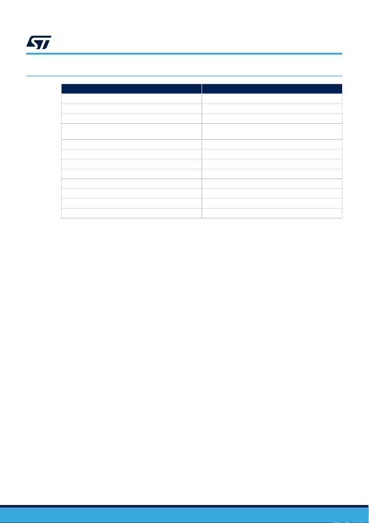
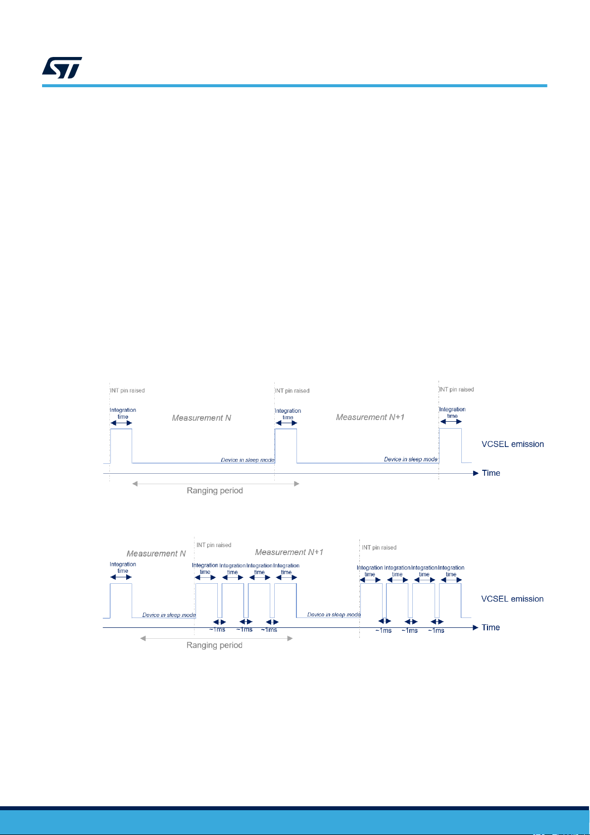
4.6 Integration time
Integration time is a feature only available using Autonomous ranging mode (refer to Section 4.5 Ranging mode).
It allows the user to change the time while VCSEL is enabled. Changing integration time if Ranging mode is set to
continuous has no effect. The default integration time is set to 5 ms.
The effect of integration time is different for 4x4 and 8x8 resolutions. Resolution 4x4 is composed of one
integration time, and 8x8 resolution is composed of four integration times. The following figures represent the
VCSEL emission for both resolutions.
Figure 9. Integration time for 4x4 autonomous
Figure 10. Integration time for 8x8 autonomous
The sum of all integration times + 1 ms overhead must be lower than the measurement period. Otherwise the
ranging period is automatically increased.
UM3109
Ranging mode
UM3109 - Rev 1 page 10/20
Table des matières
Autres manuels ST Capteur de sécurité


