6
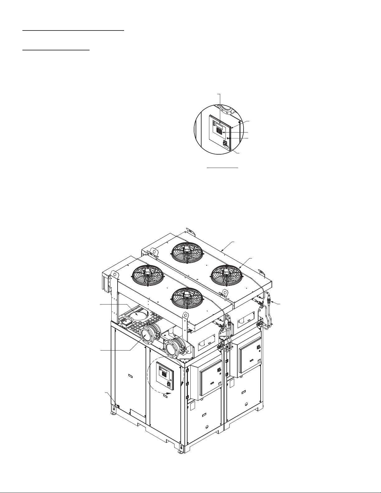
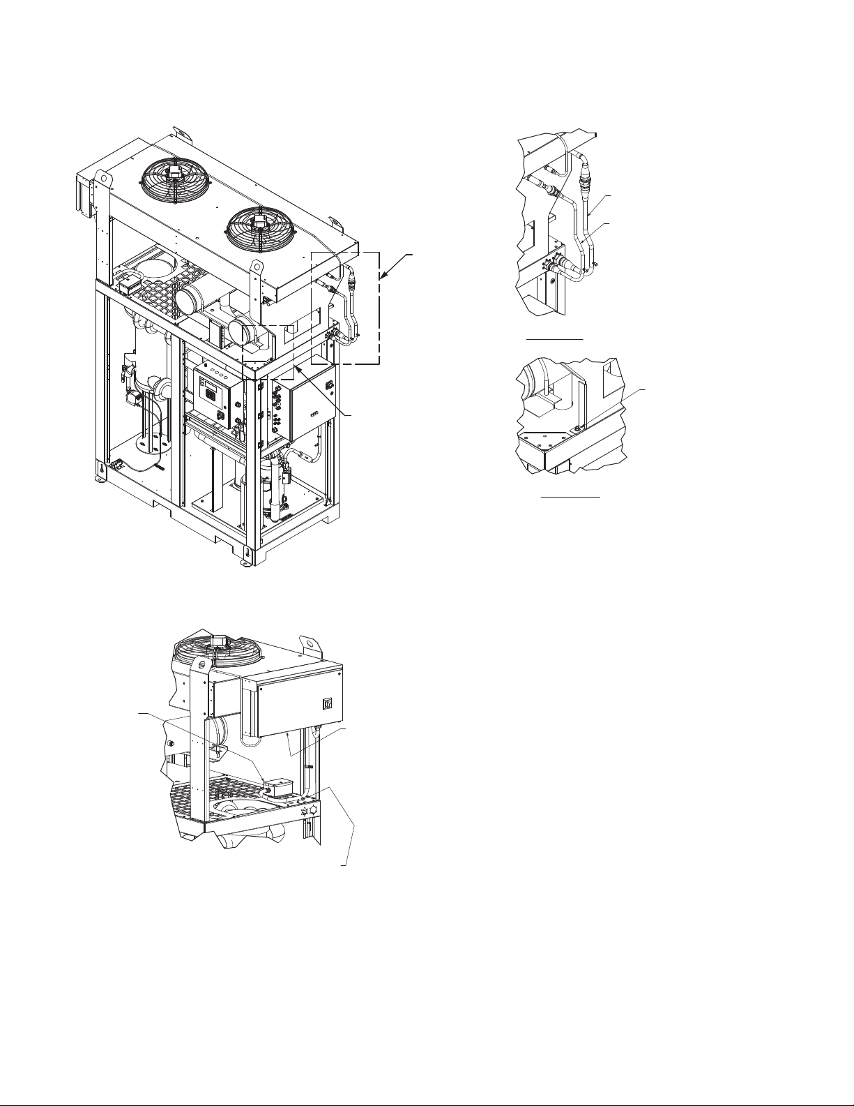
3.3 ADDITIONAL INSTALLATION PROCEDURE FOR AIR
COOLED CONDENSER OPTION
A. Air Condenser – Locate air condenser and set condenser
with brackets on top of unit. Locate brackets per drawing
on following page and bolt to frame using Qty (4) 3/8-16
Bolt’s supplied.
B. Install discharge and liquid refrigerant piping per drawing.
Turn until nut bottoms using quick links. Please note piping
is charged with refrigerant.
C. Wire junction box per wiring schematic reference drawing
for air cooled units in manual.
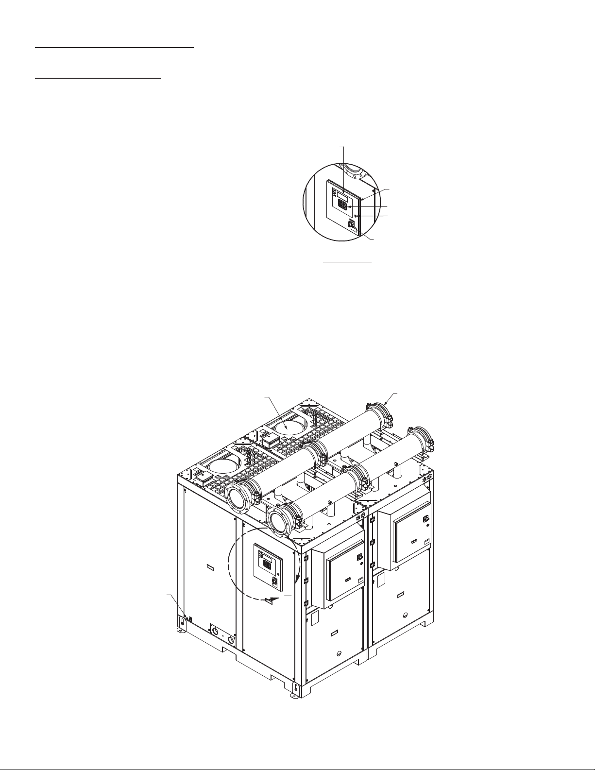
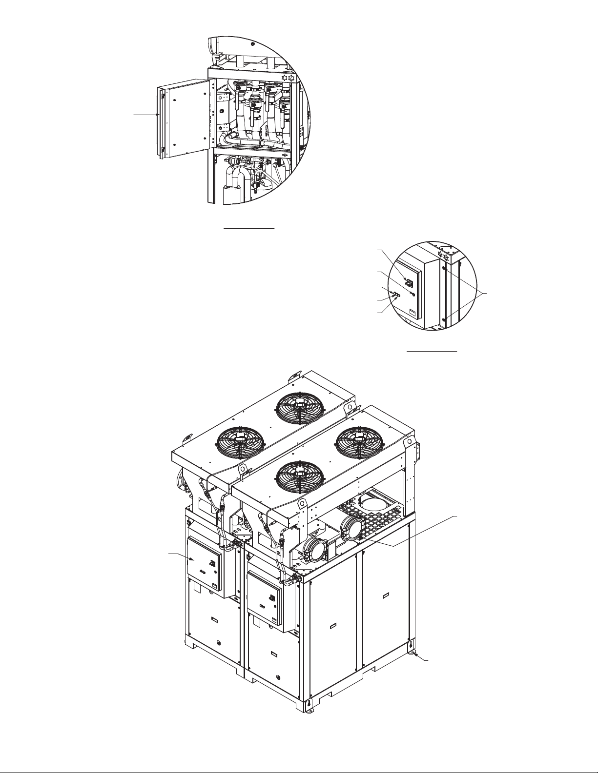
3.4 MODULE INSTALLATION
A. Identify customer-to-dryer connection requirements.
NOTE: Inlet and outlet headers on the dryer offer dual
installation capability. Either end of the header (inlet or
outlet) may be equipped with an adaptor ange or blind
ange for the customer connection.
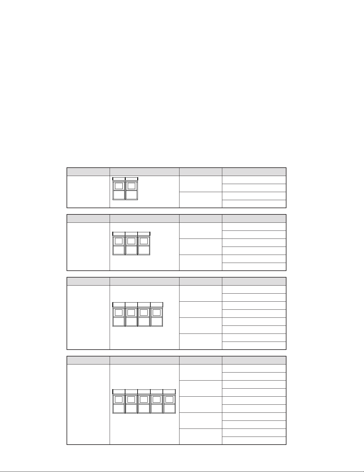
B. Install a grooved adapter ange to the inlet header of the
module which is to be connected to the customer inlet con-
nection. (Refer to the General Arrangement drawing for
the specic model in Section 8 or 9 of this manual for the
correct Inlet location.)
C. Install a grooved adapter ange to the outlet header of the
module which is to be connected to the customer outlet
connection. (Refer to the General Arrangement drawing
for the specic model in Section 8 or 9 of this manual for
the correct Outlet location.)
D. NOTE: Be sure that the leveling feet are seated completely
against the bottom of the cabinet prior to setting the module.
This will allow the greatest range of adjustment.
Utilizing a standard oor jack and the fork channels con-
structed in the base pan of each module, align the module
with the grooved adapter ange on the inlet connection
with the customer’s inlet connection.
Level and plumb the module by adjusting the leveling feet
at the bottom of each module.
IMPORTANT: READ PRIOR TO STARTING THIS EQUIPMENT
3.0 INSTALLATION
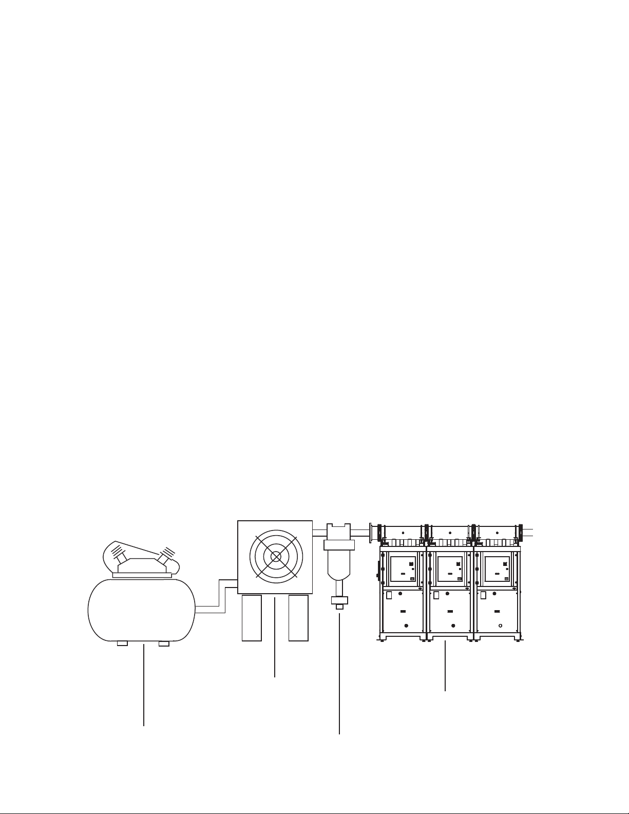
3.1 LOCATION
A. For typical placement in a compressed air system, see
drawing.
B. Air compressor intake – Locate the air compressor so that
contaminants potentially harmful to the dryer (e.g. ammo-
nia) are not drawn into the air system.
C. The dryer should be installed in a moderately heated, well
ventilated area. Avoid locations immediately adjacent to
cold exterior windows or walls, or adjacent to high tem-
perature ovens or boilers.
D. The dryer should be installed in the air system at the high-
est air pressure possible (e.g. before pressure reducing
valves).
E. The dryer should be installed in the air system at the cool-
est compressed air temperature possible.
F. Clearances:
Service clearance should be a minimum of 48 inches
(1220 mm) on all sides to allow adequate space for access
and maintenance. Recommended overhead clearance is
36 inches (914mm) from top of cabinet for water cooled
unit and top of condenser for air cooled unit.
G. Standard units are designed to operate in ambient:
Water-cooled: 40 to 130°F (4 to 54°C)
Air-cooled: 40 to 110°F (4 to 43°C).
H. Dryer is designed to operate at all altitudes - no adjust-
ment for altitude is required.
I. The installation of a exible connection prior to the dryer is
recommended to prevent possible damage from vibration.
NOTE: Outdoor installation – Standard units are designed for
indoor installation. Contact manufacturer if installing outdoors.
3.2 MOUNTING
Mount the dryer on a level solid surface.
Aftercooler
Separator
Dryer
Compressor